TM5-6115-593-34
NAVFAC P-8-631-34
TO-35C2-3-463-2
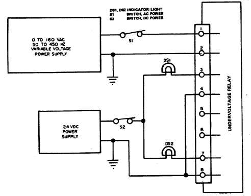
Figure 5-10. Undervoltage Relay K111, Test Setup.
Repeat the test with the input connected to
2 and 4, and then again, between 3 and 4
by rotating switch S2. The trip points should
be within 1 volt of each other.
NOTE
Disconnect relay from test setup.
(d)
With an ohmmeter, check that terminals 5,
6, 7, and 8, and terminals 1, 2, 3, and 4 are
electrically isolated with the relay in either
position.
(2)
Replacement. Remove relay (71, figure 5-1,
sheet 2) by disconnecting and tagging wires,
and removing four screws (70).
h.
Overload Relay K114 (62, figure 5-1)
(1)
Test
(a)
Connect the relay in the test setup shown in
figure 5-13.
(b)
With the 120/208V AC power source
energized, turn on the 24V DC power and
close switch S1. Lamp DS1 shall light and
DS2 shall be extinguished.
(c)
Adjust autotransformer T1, T2, and T3 until
ammeters A1, A2, and A3 indicate 0.75
ampere. DS1 and DS2 shall not change
states.
(d)
Adjust autotransformer T1 until ammeter A1
indicates 0.975 ampere. After 8 2
minutes, DS1 and DS2 must transfer states,
if not, replace.
(e)
Repeat step (d) for auto-transformers T2
and T3. The test shall be the same as for
T1.
(2)
Replacement. Remove relay (62, figure 5-1,
sheet 2) by disconnecting and tagging wires and
removing two screws (61).
5-13