TM5-6115-593-34
NAVFAC P-8-631-34
TO-35C2-3-463-2
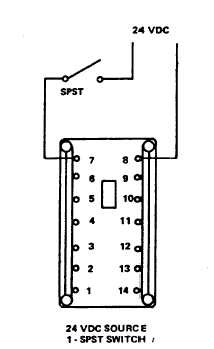
Figure 5-6. Relay K23, Test Setup
relay. Set the frequency at 50 Hz and
increase the voltage to 156 volts. DS1 shall
extinguish and DS2 shall light. Repeat for
the same voltage.
NOTE
Disconnect relay from test setup.
(g)
Using an ohmmeter, set on high scale,
connect one lead to the relay case and the
other lead to relay terminals one at a time.
Meter should read no continuity. Similarly,
connect ohmmeter between terminal 1 and
3, 4, 5, and terminal 1 and 6, 7, 8. There
should be no meter reading.
(2)
Replacement. Remove (69, figure 5-1, sheet
2) by disconnecting and tagging wires and
removing four screws (68)
c.
Phase Sequence Relays K103 (60, Figure 5-1).
(1)
Test. To test relays K103, connect as shown
in test setup, figure 5-8. This relay operates
on 190-520 volt, 3-phase, 60 Hz. When
incorrect phase sequence A, C, B (figure 5-8),
is applied the relay will energize until power is
removed. Ohmmeter connected to terminals
4 and 5 will indicate continuity at this point
until the correct phase sequence is applied,
then an open circuit will appear at terminals 4
and 5.
(2)
Replacement. Remove relay (60, figure 5-1,
sheet 2) by disconnecting and tagging wires
and removing four screws (59).
d.
Sync Check Relay K106 (82 Figure 5-1).
(1)
Test. To test relay K106, connect as shown in
test setup, figure 5-9. Two separate 115V AC
sources are required: (1) a fixed frequency
115V AC 50/60 HZ source, and (2) a variable
frequency 115V AC source. Two lamps
connected in parallel across the two sources
are also required. When the lamps turn off
together,
the
115V
AC
sources
are
synchronized. The ohmmeter must show
continuity, indicating that the relay contacts
are closed. Perform this test at both 50 and
60 HZ frequencies. If lights fail to turn off
together while variable frequency source is
within tolerance (47.5 to 52.5 Hz for 50 Hz
test, 57.5 to 62.5 Hz for 60 Hz test), K106 is
defective and must be replaced.
(2)
Replacement. Remove relay (82 figure 5-1,
sheet 2) by disconnecting and tagging wires
and removing four screws (81).
e.
Undervoltage Relay K111 (78, figure 5-1).
(1)
Test. To test undervoltage relay K111,
connect relay as shown in test setup figure 5-
10.
5-9


