TM5-6115-593-34
NAVFAC P-8-631-34
TO-35C2-3-463-2
close locking device (under relay
socket) and lift relay out of socket. To
replace, plug in snugly, until locking
device is firmly in place.
b.
Overvoltage Relay K102 (69, figure 5-1).
(1)
Test. To test relay K102, connect
relay as shown in test setup figure 5-
7.
(a)
Connect a variable 0 to 160V
AC
source
and
variable
frequency (50 to 60 Hz) source
to! terminals 1 and 2 with switch
S1 in series.
(b)
Connect lamps DS1 and DS2,
switch S2, and a 24V DC supply
as shown in figure 5-7.
(c)
Close S1 and S2. Set voltage
to 120 volts on terminals 1 and
2 and vary the frequency from
50 to 60 Hz. DS1 shall stay lit
and
DS2
shall
remain
extinguished.
(d)
Slowly increase the voltage to
140 volts. Vary the frequency
from 50 to 60 Hz. DS1 shall
stay lit and DS2 shall remain
extinguished.
(e)
Slowly increase the voltage to
154 volts. Vary the frequency
from 50 to 60 Hz. DS1 shall
stay lit and DS2 shall remain
extinguished.
(f)
After
each
light
transfer,
remove AC power to clear the
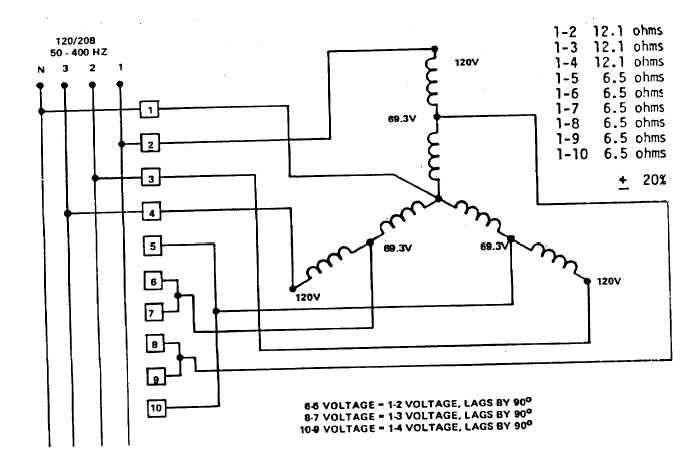
Figure 5-5. Transformer T103, Schematic
5-8