TM5-6115-593-34
NAVFAC P-8-631-34
TO-35C2-3-463-2
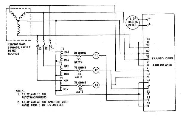
Figure 5-2. Transducers A107 and A108, Test Setup
(d)
Connect
lead
wires,
then
remove tags.
(2)
Replace transducer A103 (31, figure
5-1) as follows:
NOTE
Transducer A103 and the generator set
frequency meter must be replaced as a
matched set.
(a)
Replacement of the frequency
meter is within the scope of
Organizational
Maintenance,
and is performed in accordance
with
Operator
and
Organizational
Maintenance
Manual.
(b)
Tag and disconnect lead wires
to A103.
(c)
Remove screws (29) and nuts
(30) to remove transducer (31).
(d)
Secure replacement transducer
(31) using screws (29) and nuts
(30)
(e)
Connect wires to A103 and then
remove tags.
5-3. TRANSFORMERS.
WARNING
BEFORE
STARTING
ANY
MAINTENANCE
PROCEDURE,
SET
MAINTENANCE LOCKOUT SWITCH TO
LOCKOUT. DISCONNECT NEGATIVE
CABLE FROM BATTERIES. REMOVE
EXTERNAL
POWER
BY
OPENING
CB101 (EXTERNAL POWER CIRCUIT
BREAKER)
AND
DISCONNECTING
POWER CABLE FROM RECEPTACLE
J101 (120V RECEPTACLE)
a.
Transformers T101 and T102, Testing (56
and 58, figure 5-1). Remove transformers
according to
5-5