TM5-6115-593-34
NAVFAC P-8-631-34
TO-35C2-3-463-2
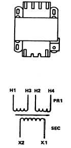
Figure 5-4. Transformers T101 and T102, Schematic
c.
Replacement.
Transformers T101, T102, and T103 (56, 58
and 80 figure 5-1, sheet 2) are removed
from the control cubicle base assembly by
disconnecting
and
tagging
wires,
and
removing four screws (66) on transformer
(79).
5-4. RELAYS. Relays K23, K102, K103, K106, K111,
K112, K113, and K114 are mounted at the base of the
control cubicle. Refer to figure 5-1, sheet 2.
RELAY
ITEM NO.
FUNCTION
K23
63
24V DC
K102
69
Overvoltage
K103
60
Phase Sequence
K106
82
Synch Check
K111
78
Undervoltage
K112
67
Reverse Power
K113
71
Short Circuit
K114
62
Overload
WARNING
BEFORE
STARTING
ANY
MAINTENANCE
PROCEDURE,
SET
MAINTENANCE LOCKOUT SWITCH TO
LOCKOUT. DISCONNECT NEGATIVE
CABLE FROM BATTERIES. REMOVE
EXTERNAL
POWER
BY
OPENING
CB101 (EXTERNAL POWER CIRCUIT
BREAKER)
AND
DISCONNECTING
POWER CABLE FROM RECEPTACLE
J101 (120V RECEPTACLE).
a.
24V DC Relay K23 (63, figure 5-1).
(1)
Test relay K23 by connecting 24V DC
and a single-pole single-throw switch
as shown in figure 5-6.
(a)
Close SPST switch. With an
ohmmeter, check for an open
circuit between terminals 1 and
2 and terminals 13 and 14.
Meter should indicate continuity
between terminals 3 and 4,
terminals 5 and 6, and terminals
11 and 12.
(b)
Open SPST switch. With the
ohmmeter, check for continuity
between terminals 1 and 2 and
terminals 13 and 14. Meter
should indicate an open circuit
between terminals 3 and 4,
terminals 5 and 6, and terminals
11 and 12. If relays fail this
check, replace in accordance
with (2), below.
(2)
Replacement. Relay K23 is a plug-in
type relay mounted in a socket on the
box assembly panel at the base of the
control cubicle. To remove,
5-7