TM5-6115-593-34
NAVFAC P-8-631-34
TO-35C2-3-463-2
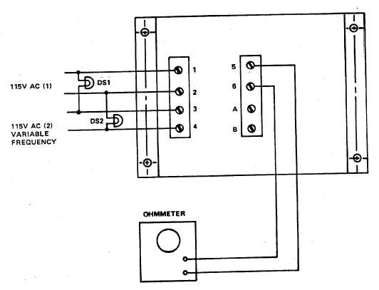
Figure 5-9. Sync Check Relay K106, Test Setup
on terminals 1 and 2 to 0.05 amp.
(b)
Turn
the
adjusting
potentiometer
fully
clockwise.
(c)
Push the Press-to-test Button.
(d)
Turn the adjusting potentiometer slowly
counterclockwise until the contact between
terminals 3 and 5 closes. Stop at that point
and release the Press-to-test Button.
(e)
Wait 15 seconds and push the Press-to-test
Button. The contact between terminals 3
and 5 must close after an interval of
approximately 4 to 5 seconds.
(3)
Replacement. Remove relay (67, figure 5-1,
sheet 2) by disconnecting and tagging wires and
removing four screws (66).
g.
Short Circuit Relay K113 (71, figure 5-1).
(1)
Test.
(a)
Connect the relay in the test setup shown in
figure 5-12.
(b)
Connect a lamp and a 24V DC power supply
in series with terminals 5 and 6 (DS1), also
with terminals 7 and 8 (DS2) and switch S3.
Relay trip will be indicated by the two lamps:
DS1 shall extinguish; DS2 shall light.
(c)
Connect a variable 0 to 120V AC source (50
to 60 Hz) between terminals 1 and 4 and
slowly increase the voltage. The relay shall
transfer lights when voltage equals 24 volts
± volt.
5-12