TM5-6115-593-34
NAVFAC P-8-631-34
TO-35C2-3-463-2
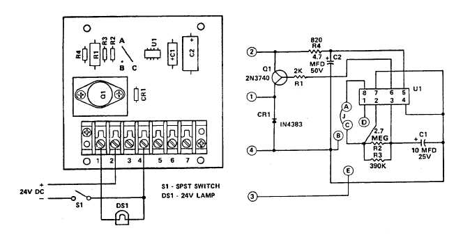
Figure 5-14. Time Delay TD2, Test Setup
(f)
If components are to be replaced, carefully
solder new component into place.
(g)
Install time delay assembly (87) by securing
brackets (84) using screws (83).
(h)
Connect wires to terminal boards, then
remove wire tags.
j.
Control Relay Assembly TB10 (92 figure 5-1)
(1)
Test.
(a)
Connect control relay assembly as shown in
figure 5-15.
(b)
Close switch S1. With ohmmeter (Rx1
scale)
check
for
continuity
between
terminals 1 and 5, and terminals 2 and 4. If
ohmmeter shows no continuity, TB10 is
defective and must be replaced.
(c)
Open switch S1, close switch S2. With the
ohmmeter, check for continuity between
terminals 7 and 9. If ohm meter shows no
continuity, TB10 is defective and must be
replaced.
(2)
Replacement.
(a)
Tag and disconnect lead wires to TB10 (92,
figure 5-1).
(b)
Remove assembly (92) by removing screws
(88).
(c)
Release assembly (92) from brackets (89)
by removing screws (90) and nuts (91).
(d)
Prepare new TB10 assembly for installation
by attaching brackets (89) using screws (90)
and nuts (91).
(e)
Install TB10 (92) using screws (88).
(f)
Connect lead wires and remove wire tags.
5-5. RESISTOR ASSEMBLY TB 107. The resistor
assembly TB107 (detail C, figure 5-1, sheet 2) is
mounted to the left inside wall of the enclosure.
5-17