TM5-6115-593-34
NAVFAC P-8-631-34
TO-35C2-3-463-2
a
non-replaceable
component,
proves
defective (test 2, above), the entire assembly
must be replaced.
(4)
Replacement.
(a)
Tag and disconnect wires to TD2 (87, figure
5-1).
(b)
Remove screws (83) to remove assembly
(87) with brackets (84).
(c)
Individual components are replaced by
carefully unsoldering them from the printed
circuit board.
CAUTION
Do not apply excessive heat when
soldering
or
unsoldering
components. It may damage the
printed circuit wiring.
(d)
If TD2 is to be replaced as an assembly,
remove screws (85) and nuts (86) to release
time delay assembly (87) from brackets
(84).
(e)
Prepare TD2 assembly (87) for installation
by attaching brackets (84) using screws (85)
and nuts (86).
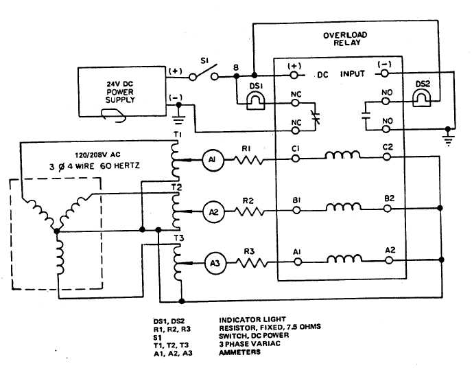
Figure 5-13. Overload Relay K114, Test Setup
5-16

