TM5-6115-593-34
NAVFAC P-8-631-34
TO-35C2-3-463-2
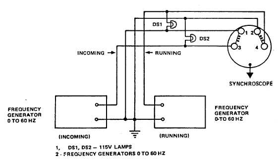
Figure 5-17. Synchroscope, Test Setup
component. If the printed circuit wiring or a terminal
board proves defective, or a nonreplaceable component
is defective, the entire assembly must be replaced.
c.
Replacement.
(1)
Remove relay assembly (76, figure 5-1) as
follows:
(a)
Tag
and
then
disconnect
wires
from
terminal boards.
(b)
Remove screws (72) to remove relay
assembly (76) and brackets (73).
(c)
Components are replaced by carefully
unsoldering them from the printed circuit
board.
CAUTION
Do not apply excessive heat when
soldering
or
unsoldering
components. It may damage the
printed circuit wiring.
(d)
If Annunciator Control Relay Assembly is to
be replaced; remove screws (74) and nuts
(75) to release relay assembly (76) from
brackets (73).
(e)
Prepare relay assembly (76) for installation
by attaching brackets (73) using screws (74)
and nuts (75).
(f)
If components are being replaced, carefully
solder new component into place.
(g)
Install relay assembly (76) by securing
brackets (73) using screws (72).
(h)
Connect wires to terminal boards, then
remove wire tags.
5-7. FLASHING CIRCUIT FC1 . The flasher (20, figure
5-1, sheet 1) is mounted on the inside right wall of the
enclosure and plugs into a terminal block assembly (21).
Remove flasher and check by connecting it in series
with a 24V DC power source and test lamp. If the
flasher is good, the test lamp should flash. If not,
replace by plugging new flasher into place.
5-21