TM5-6115-593-34
NAVFAC P-8-631-34
TO-35C2-3-463-2
(d)
Open
switch
S1.
Adjust
frequency
generator for 60 Hz output.
(e)
Decrease frequency generator frequency to
58.2 Hz. With ohmmeter connected
between terminals 5 and 6, relay should trip
at 58.2 Hz (57.7 to 58.7 Hz), at which time
ohmmeter will no longer show continuity.
(f)
Turn adjustment screw clockwise to raise
trip point.
(2)
REPLACEMENT. Remove relay (9, figure 5-
19) by disconnecting and tagging wires and
removing four screws (1).
b.
Overfrequency relay 81GO (8, figure 5-19).
(1)
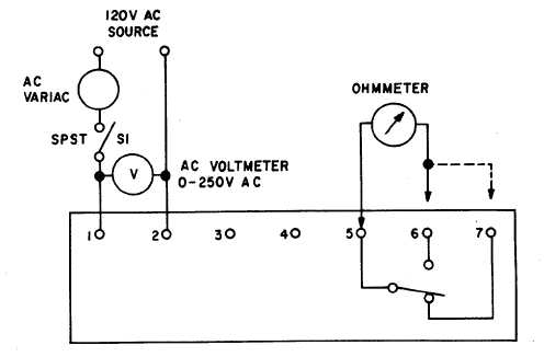
Test the overfrequency relay by connecting as
shown in figure 5-20.
(a)
Close switch S1.
(b)
Adjust variable frequency generator for 50.0
Hz output.
(c)
With
ohmmeter
connected
between
terminals
5
and
7,
adjust
frequency
generator to 51.5 Hz (51 to 52). At this
point, relay should trip. Ohmmeter will no
longer show continuity.
(d)
Open switch S1.
(e)
Set frequency generator output to 60.0 Hz
and connect ohmmeter between terminals 5
and
6.
Ohmmeter
should
indicate
continuity. Increase frequency generator
output to 61.8 Hz: relay should trip at 61.8
Hz (61.3 to 62.3) and ohmmeter should
indicate infinite ohms.
(f)
Turn adjustment screw clockwise to raise
trip point.
(2)
REPLACEMENT. Remove relay (8, figure 5-
19) by disconnecting and tagging wires and
removing four screws (1).
c.
Over/under voltage relay 27/59G (7, figure 5-
19).
Figure 5-21. Over/under Voltage Device, Test Setup
5-26