TM5-6115-593-34
NAVFAC P-8-631-34
TO-35C2-3-463-2
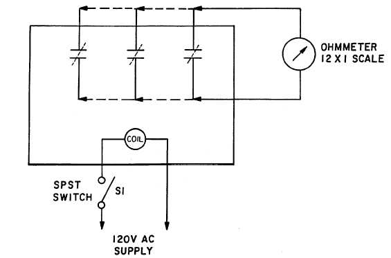
Figure 5-22. Relay Test Setup
(1)
Test the relay by connecting as shown in
figure 5-21.
(a)
Close S1 and adjust variac for 110V AC as
indicated by A.C. voltmeter.
(b)
With
ohmmeter
connected
between
terminals 5 and 7, reduce AC voltage.
Relay should trip at 108V AC. At this point,
ohmmeter will no longer show continuity.
(c)
With
ohmmeter
connected
between
terminals 5 and 6 adjust AC voltage source
to read 130V AC on voltmeter.
(d)
Increase voltage to 133V AC, relay should
trip at 132V AC. Ohmmeter will no longer
show continuity.
(2)
REPLACEMENT. Remove relay (7, figure 5-
19) by disconnecting and tagging wires and
removing four screws (1).
d.
RELAYS, BCR, CR AND BTR (2, 6, and 4,
figure 5-19).
(1)
Test any of the three relays by connecting as
shown in figure 5-22.
(a)
Close switch S1.
(b)
Using the ohmmeter, verify that all normally
open contacts have closed (zero resistance
on meter) and all normally closed contacts
have opened (infinite resistance on meter).
(2)
REPLACEMENT. Remove relays (2, 6 or 4,
figure 5-19) by disconnecting and tagging
wires and removing two screws (1).
e.
SRM, SYNCHRONIZING RELAY (3, figure 5-
19)
(1)
Test the SRM relay by connecting as shown in
figure 5-23, synchronizing test.
(a)
With 115V AC supplied, contacts 9 and 10
shall close causing ohmmeter to read zero
ohms resistance.
5-27