TM5-6115-593-34
NAVFAC P-8-631-34
TO-35C2-3-463-2
a.
Test. Test by disconnecting one lead from each
resistor. With an ohmmeter, check each
resistor for 7.5 ohms 0.5 percent.
b.
Replacement. Remove resistors by unsoldering
leads and removing from clips.
5-6. ANNUNCIATOR CONTROL ASSEMBLY TB6 (76,
figure 5-1). The annunciator control relay assembly
contains four terminal boards, 20 diodes, and 13 relays:
REF DES
FUNCTION
K25A
Alarm Silence
K25B
Alarm Silence
K26
Alarm Arming
K27
High
Coolant
Temperature
K28
High Oil Temperature
K29
Low Oil Pressure
K30
Low Fuel Level
K31
Overspeed
K32
Overvoltage
K33
Undervoltage
K34
Reverse Power
K35
Overload
K36
Short Circuit
a.
Test.
(1)
Check each relay using test circuits shown in
figure 5-16. Energize each set of relay
contacts individually by applying 24V DC
directly to leads. Check for open or closed
contacts (no continuity or continuity) as
indicated in figure 5-16. Check that each set
of contacts revert (to either closed or open
position) when deenergized. If only relay fails
to either open or close as indicated, it is
defective and must be replaced.
(2)
Check diodes for polarity. A good diode will
read high resistance one way and low
resistance the other way. A defective diode
will read full scale both ways, or will read
infinity (no reading) in either direction.
(3)
Check terminal boards and printed circuit
wiring by repeating steps (1) and (2), but apply
24V DC to TB6 terminals.
b.
Repair. If any of the relays or diodes are
defective, Annunciator Control Relay Assembly
TB6 is repairable by replacing the defective
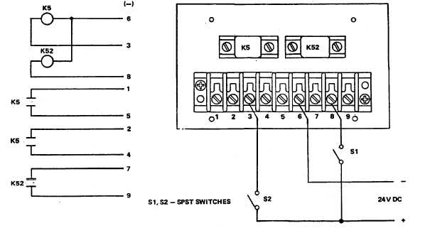
Figure 5-15. Control Relay Assembly TB10, Test Setup
5-18


