TM5-6115-593-34
NAVFAC P-8-631-34
TO-35C2-3-463-2
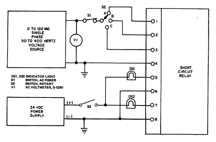
Figure 5-12. Short Circuit Relay K113, Test Setup
board, or a non-replaceable component,
proves defective (test 2, above), the entire
assembly must be replaced.
(4)
Replacement.
(a)
Tag and disconnect wires to TD2 (87, figure
5-1).
(b)
Remove screws (83) to remove assembly
(87) with brackets (84).
(c)
Individual components are replaced by
carefully unsoldering them from the printed
circuit board.
(2)
Test of TD2.
(a)
Connect time delay circuit as shown in
figure 5-14.
WARNING
BEFORE
STARTING
ANY
MAINTENANCE PROCEDURE, SET
MAINTENANCE LOCKOUT SWITCH
TO
LOCKOUT.
DISCONNECT
NEGATIVE
CABLE
FROM
BATTERIES. REMOVE EXTERNAL
POWER
BY
OPENING
CB101
(EXTERNAL
POWER
CIRCUIT
BREAKER) AND DISCONNECTING
POWER CABLE FROM RECEPTACLE
J101 (120V RECEPTACLE).
(b)
Close switch S1. Time the period it takes
before lamp DS1 lights. It must be 3.5 to
4.5 seconds or TD is defective.
(3)
Repair. If any of the replaceable components
tested in 1 (above) are defective, TD2 is
repairable
by
replacing
the
defective
component. If the printed circuit wiring or a
terminal board, or
5-15