TM5-6115-593-34
NAVFAC P-8-631-34
TO-35C2-3-463-2
(2)
Replacement. Remove relay (78, figure 5-1,
sheet 2) by disconnecting and tagging wires and
removing four screws (77).
f.
Reverse Power Sensing Relay K112 (67, figure
5-1).
NOTE
Check relay K112 fuse prior to
performing the following tests.
(1)
Polarity and Reverse Power Circuit Test.
NOTE
Ensure
that
the
adjusting
potentiometer is set fully clockwise
before starting this test.
(a)
Connect a 0 to 1.2 amp, 0.05V AC
maximum, power source to terminals 1 and
2 (see figure 5-11). Connect a 115V AC, 60
Hz source to terminals 6 and 7. Connect an
ohmmeter to terminals 4 and 5.
(b)
Adjust
the
0.05V
AC
power
source
(terminals 1 and 2) to 1 amp.
(c)
Turn
the
adjusting
potentiometer
fully
counterclockwise.
(d)
If the contact between terminals 3 and 5
closes, then the polarity is incorrect and the
wires on terminals 6 and 7 must be
reversed, and the test must be started over.
(e)
Push the Press-to-test Button. The contact
between terminals 3 and 5 must close at
this time.
(2)
Inverse Time Trip Curves Test.
(a)
Set the current source
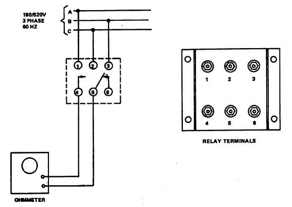
Figure 5-8. Phase Sequence Relay K103, Test Setup
5-11