TM5-6115-593-34
NAVFAC P-8-631-34
TO-35C2-3-463-2-
paragraph 5-3 c and test as follows:
(1)
Referring to figure 5-4, use an
ohmmeter and check for continuity
between
terminals
H1
and
H2,
terminals H2 and H4, and terminals
X2 and X1.
(2)
With ohmmeter set on high scale,
check
for
no
continuity
between
terminals H1 and H3, and terminals
H2 and X2.
(3)
Connect a 240 volt input with the coils
in parallel and check for 120 volt
output.
(4)
Connect a 480 volt input with the coils
in series and check for 120 volt
output.
(5)
If transformers do not meet above
check, replace them.
b.
Transformer T103 (80, figure 5-1). Remove
T103 according to paragraph 5-3 c and test
as follows:
(1)
Refer to figure 5-5 and apply 120V AC
between terminals 1 and 2. Use a
voltmeter
to
check
for
indicated
voltages (within 3 percent) at test
points shown.
(2)
Repeat procedure with inputs at
terminals 1 and 3, and at terminals 1
and 4.
(3)
If transformer T103 fails to provide
any of the indicated voltages, it is
defective and must be replaced.
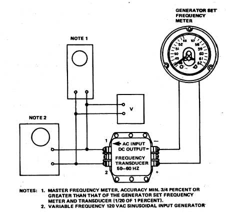
Figure 5-3. Transducer A103, Test Setup
5-6