TM5-6115-593-34
NAVFAC P-8-631-34
TO-35C2-3-463-2
i.
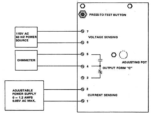
Time delay TD2 (87, figure 5-1).
(1)
Tests for Replacement Components. Check
the following components on TD 2, figure 5-
14.
(a)
Check transistor Q1 by connecting to
transistor tester and testing for current gain
or 100 min, leakage, or short.
(b)
Check capacitors C1 and C2 by connecting
each to a capacitor tester and checking for
leakage and capacitance. C1 must read 10
microfarads, 25 volts, ±5 percent. C2 must
read 47 microfarads, 50 volts, ±10 percent.
(c)
Check resistors, using an ohmmeter, for the
following resistances.
R4
820 ohms, 25 watts, ±5 percent
R1
2 k megohms, 1 watt, ±5 percent
R2
2.7 megohms, 25 watts, ±5 percent
R3
390 k, 0.25 watt, ±5 percent
WARNING
BEFORE
STARTING
ANY
MAINTENANCE PROCEDURE, SET
MAINTENANCE LOCKOUT SWITCH
TO
LOCKOUT.
DISCONNECT
NEGATIVE
CABLE
FROM
BATTERIES. REMOVE EXTERNAL
POWER
BY
OPENING
CB101
(EXTERNAL
POWER
CIRCUIT
BREAKER) AND DISCONNECTING
POWER CABLE FROM RECEPTACLE
J101 (120V RECEPTACLE).
(2)
Test of TD2.
(a)
Connect time delay circuit as shown in
figure 5-14.
(b)
Close switch S1. Time the period it takes
before lamp DS1 lights. It must be 3.5 to
4.5 seconds or TD is defective.
(3)
Repair. If any of the replaceable components
tested in 1 (above) are defective, TD2 is
repairable
by
replacing
the
defective
component. If the printed circuit wiring or a
terminal
Figure 5-11. Reverse Power Relay K112, Test Setup
5-14