
TM 5-6115-400-12
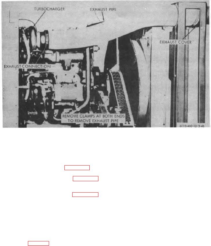
Figure 3-48. Exhaust pipe, removal and installation.
Section XII. ENGINE ELECTRICAL SYSTEM
3-56. Starting Motor and Solenoid Switch
(3) When a high charging rate with fully charged
batteries is indicated, disconnect field jumper. If
output remains high, fault is in generator and it
a. On Equipment Testing. Refer to figure 3-49 and
must be replaced. If output drops to zero, fault
test starting motor and solenoid switch.
is in generator regulator and it must be adjusted
b. Removal and Installation. Refer to figure 3-50
or replaced.
and remove starting motor and solenoid switch from
engine as an assembly.
(4) When a low or no-charging rate with partially or
c. Solenoid Switch Removal. Refer to figure 3-50
fully discharged batteries is indicated, inspect
and remove solenoid switch from starting motor.
for loose connection or defective wiring. If none,
stop engine and disconnect field jumper.
3-57. Generator
(5) Polarize generator by momentarily connecting a
a. On Equipment Testing. Refer to figure 3-51 and
jumper wire between generator field terminal
test generator regulator together as follows:
and positive terminal of batteries.
(1) Install a suitable adapter between the
receptacles of the generator and cabling.
(6) Reconnect field jumper and start engine. If
(2) Start engine (para 2-12).
charging rate does not increase as engine speed
3-54