
TM 5-6115-400-12
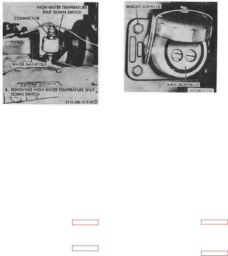
Figure 3-56. Slave receptacles, removal and
installation.
Figure 3-55 (2)Continued.
A specific gravity of 1.250 will permit the battery to
3-62. Batteries
withstand temperatures as low as -65F.
without
a. General.
The battery compartment located
freezing.
below the radiator contains four 12 volt batteries
d. Water : Addition. The electrolyte level should
connected in series-parallel to provide 24 volt current.
be maintained 3/8 inch above the separators or
b. Removal and installation. Refer to paragraph 2-
insulators by addition of distilled water or "approved
4 for removal and installation of lotteries.
water" (water free from impurities by analysis). Do not
c. Testing. The battery should be tested with a
overfill or under fill the cells of the battery as either has
hydrometer and kept to a specific gravity of 1.250 or
a detrimental effect on battery life.
above. Always test a battery for degree of charge
Note. Use of a mirror is recommended when
before adding water. The specific gravity between the
checking electrolyte level in batteries.
cells should be within .025. A dangerously low point of
e. Charging. The charging rate is correct when the
charge indicated by a hydrometer reading of 1.150 or
battery maintains a minimum specific gravity of 1.250
less will permit the battery to freeze at temperatures
and does not require the addition of more than 1 ounce
only a few degrees below the freezing point of water.
of water per cell per week or 50 service hours.
Section XIII. ENGINE CONTROLS AND INSTRUMENTS
3-65. Gages
3-63. Battery-Charging Ammeter
Removal and Installation. Refer to figure 3-57 for
Removal and Installation. Refer to figure 3-57 and
removal of the fuel level gage, coolant temperature
remove the battery-charging ammeter.
gage, and the engine oil pressure gage.
3-64. Time Totalizing Meter
3-66. Engine Control Switches
Removal and Installation. Refer to figure 3-57 and
Removal and Installation. Refer to figure 3-57 for
remove the totalizing meter.
removal of the engine primer switch and the engine
start-run-stop switch.
3-58