
TM 5-6115-400-12
bestos gaskets and secured in place with either nuts and
in the cylinder head. The temporary studs
washers or cap screws and washers.
are removed after the cap screws are
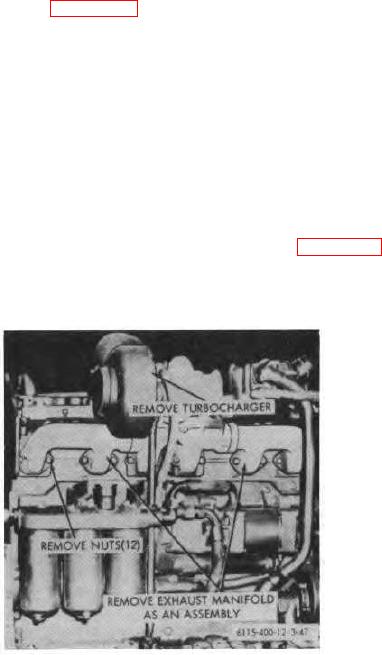
b. Removal and Installation. Refer to figure 3-47
installed. When installing the connecting
and remove manifold.
sleeves and sealing rings, be sure to
separate the position of the gaps on the
c. Exhaust Manifold Reassembly and Installation.
sealing rings to assure a proper seal.
(1) Disassemble manifold as required.
(2) Reassemble and install manifolds in the reverse
(3) Tighten the exhaust manifold cap screws to a
order of disassembly.
torque of 68 to 73 foot pounds. After engine is
operating and the water temperature reaches
Note. Always use new gaskets when
approximately 170F., again torque the cap
installing the exhaust manifold assembly
screws to the specified torque.
and
when
mounting
turbocharger.
Cement the gaskets to the manifold and
3-65. Exhaust Pipe
let them dry. Install the center section of
the three piece manifold first, using two
Refer to figure 3-48 for removal of the exhaust
temporary
studs
pipe.
Figure 3-47. Exhaust manifold, removal and
installation.
3-53