
TM 5-6115-400-12
Caution:
(8) Make certain the gaskets do not extend
Never operate engine while the air
into port openings of the intake manifold,
exhaust manifold, air inlet elbow,
inlet hose between air cleaner and
turbocharger mounting adapter, and
turbocharger or the exhaust outlet
mounting pads.
piping is disconnected. Clothing or
foreign objects can be drawn into the
(9) Just prior to mounting the unit, prime the
lubrication system. Fill the center housing
compressor inlet.
Discharged
oil reservoir with new, clean oil through
carbon particles and hot exhaust gas
the oil inlet. Turn rotating assembly by
from the turbine outlet can cause
hand to coat the bearings and thrust collar
personal injury.
with oil.
3-53. Intake Manifold
c. Turbocharger.
a. General.
(1) Install new gasket and mount the
(1) The air intake system includes the air
turbocharger on the exhaust manifold.
cleaner, the compressor side of the
Lubricate mounting studs with an
turbocharger, and the intake manifold with
antiseize compound. Install washers and
intercooler.
stud nuts.
(2) It is important to provide an ample supply
(2) Install the air cleaner to turbocharger
of fresh air to the combustion chambers.
hose.
Insufficient air will limit the amount of fuel
the engine can burn and will lead to loss
(3) Connect lower end of oil inlet hose to the
of power, excessive exhaust smoke, and
lubricating oil adapter located on side of
high fuel consumption. Contaminated air
the engine block.
leads to worn engine parts, high oil
Caution:
consumption, and eventual: engine
Do not connect the oil inlet line to
failure.
the turbocharger until step 5 is
(3) The intake manifold is sealed to the
performed.
cylinder head with steel-asbestos gaskets
(4) Remove electrical connector from fuel
and secured in place with capscrews and
solenoid at fuel injection pump.
washers.
(5) Crank engine until a free flow of oil is
b. Intake Manifold Removal.
observed, coming from upper end of the
Note.
oil inlet hose, then connect it to the
Remove head.
turbocharger oil inlet.
Refer to figure 345 and remove manifold as
(6) Continue to crank engine until oil flows
follows:
from turbocharger oil outlet.
(7) Connect lower end of drain line to the
turbocharger drain nipple on side of oil
pan.
(8) Using a new gasket, assemble upper end
of oil drain line to the turbocharger.
(9) Assemble diffuser or diffuser ring to the
turbocharger and exhaust manifold.
(10) Install exhaust elbow, exhaust pipe, and
engine hood.
(11) Reconnect electrical connector to fuel
(12) Upon completion of the installation, run
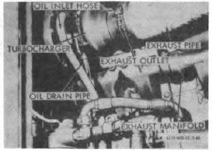
Figure 3-44. Turbocharger, removal and
engine and check turbocharger operation.
installation.
3-50