
TM 5-6115-400-12
tube hose; force hose onto bonnet tube.
Note.
If hose is too hard or inflexible to be
worked onto tube, cut hose and
remove it completely; replace with a
new hose.
(10) Remove capscrew and lockwasher
securing oil cooler support bracket to the
water inlet manifold.
(11) Remove capscrew and lockwashers
securing water manifold assembly to
water inlet manifold. With hoses intact,
lift oil cooler end up as high as possible
and wire oil cooler to the engine in this
position to allow clearance for the water
pump removal.
(12) Remove nuts and lockwashers from pump
mounting studs, slide pump body towards
Figure 3-38. Water inlet manifold, removal and
rear of engine and off
installation.
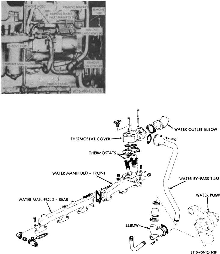
Figure 3-39. Water outlet manifold and thermostat, removal and installation.
3-46