
TM 5-6115-400-12
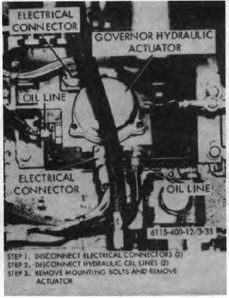
Figure 3-33. Electric governor hydraulic actuator, removal and installation.
Section X. ENGINE COOLING SYSTEM
inspections Shutters should be opened
3-42. General
and closed manually to note that vanes
The cooling system consists of a radiator, water
operate absolutely free. Vane bearing
pump, fan, thermostats, shutter and shutter controls,
should be washed with cleaning fluid and
and the necessary lines, fittings, and linkage to connect
blown out with air. Do not lubricate nylon
these components.
The flow control thermostat
vane bearings.
regulates the flow of coolant pumped through the engine
block by the water pump to cool the engine. The shutter
(2) Automatic Control.
The thermostatic
is controlled by the shutter control thermostat and can
element is mounted in the bottom tank of
also be operated manually.
radiator and operates shutter by thermal
expansion. The control is so arranged
3-43. Radiator Grill
that shutter will completely open in
Refer to figure 334 and remove the radiator grill.
approximately 8 to 10 degree range. The
3-44. Radiator Shutter and Control
thermostat opens shutter and is closed by
a. Description.
return spring. Control should be adjusted
(1) Shutter. The vanes are made of extruded
so that shutter is closed when engine is
aluminum alloy and are mounted in 5/16
cold.
inch nylon bearings. Shutters must be
checked and cleaned at
regular
3-42