
TM 5-6115-400-12
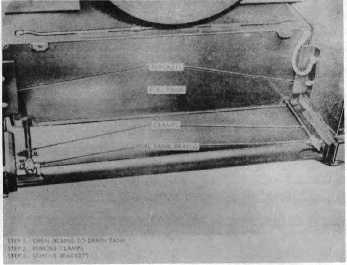
Figure 3-29 (1). Fuel tank, removal and installation.
the fuel injection pump, controls
the loosened vent screw, a clogged or collapsed fuel
maximum fuel pressure within the fuel
line is indicated. If this condition exists, replace the
battery of the injection pump. The relief
necessary fuel line.
valve is set to open between 8 and 30 psi.
c. Check for Inoperative Fuel Transfer Pump or
When fuel pressure within the fuel gallery
Fuel Pressure Relief Valve.
of the injection pump exceeds relief valve
(1) The fuel transfer pump should deliver
setting, the pressure relief valve opens
more fuel to the fuel gallery of the fuel
and allows excess fuel to return to the fuel
injection pump than is required for engine
tank through the fuel filter head and fuel
operation. The fuel pressure relief valve,
return line.
connected into the fuel return passage of
3-37