
TM 5-6115-400-12
(5) Loosen the fuel injection tube nuts from
the fuel injection line connectors.
(6) Free the injection nozzle end of the tubes
and remove the tubes from the engine.
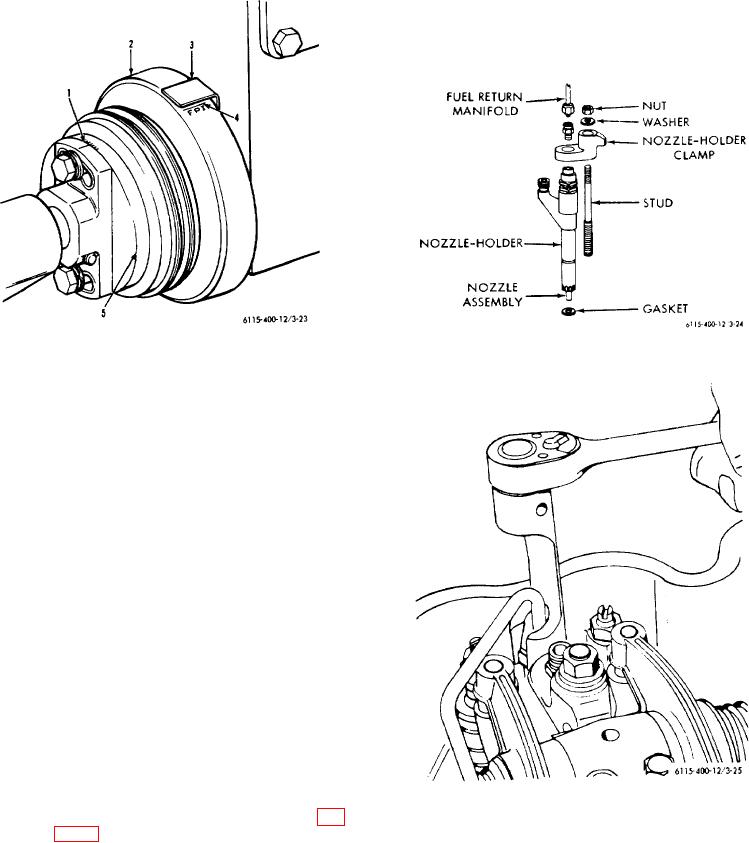
Figure 3-24. Nozzle-holder assembly.
1 Degree marks (1 marks-3 degrees) Use when
advancing or retarding pump timing to indicate
degrees changed.
2 Coupling hub
3 Timing pointer
4 FPI timing mark
5 Coupling flange
Figure 3-23. Fuel pump coupling timing marks.
holder assembly is used to hold the nozzle in its correct
position in the cylinder head and to provide a means of
conducting fuel to the nozzle. The holder assembly
consists of a holder body, spindle, spindle spring,
pressure adjusting screw, adjusting screw locknut,
protection cap, and a nozzle retaining nut. The nozzle
consists of a nozzle valve and a nozzle valve body, in
which are located four equally spaced spray orifices.
b. Removal and Installation.
(1) Thoroughly clean valve rocker covers and
surrounding area.
(2) Remove valve rocker covers.
(3) Disconnect and remove the fuel return
manifold.
Figure 3-25. Fuel injection tubes, removal and
(4) Using a fuel injection tube nut wrench (fig.
installation.
3-25), loosen the injection tube nuts from
the top of the fuel injection nozzles.
3-33