
TM 5-6115-400-12
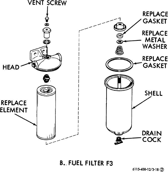
Figure 3-18 (2). Continued.
(4) Disconnect the fuel supply solenoid valve
(2) Drain day tank (TK-1, fig. 3-17).
and remove from the fuel injection pump.
(3) Before removing the pump from the
(5) Disconnect the fuel outlet hose and the
engine, make certain the FPI mark on the
fuel return and injection lines.
coupling hub is aligned with the timing
(6) Disconnect the lubrication hose.
pointer attached to the pump. This will
position the No.
1 piston on its
(7) Remove the capscrews and lockwasher
compression stroke and facilitate pump
attaching the pump to the pump
installation.
3-28