TM 5-6115-400-12
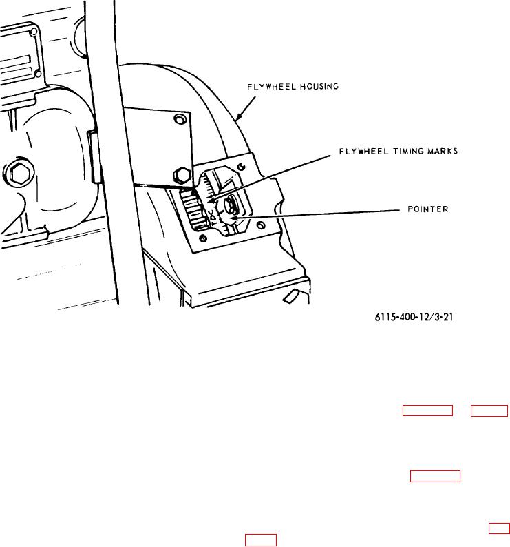
Figure 3-21. Engine timing pointer.
of the center-line of the pump camshaft to the center-
(9) If the FPI mark on the coupling hub is on
line of the driving shaft in the accessory side.
one side or the other of the pointer, it
(11) Tighten pump attaching capscrews and
must be alined, following the procedure
clamp to flange screws and recheck pump
listed below:
for alinement. (See figs. 3-20 and 3-22).
(a) Loosen the two drive coupling
(12) Connect the fuel inlet and outlet hoses
flange attaching capscrews (fig. 3-
and the fuel return and injection lines.
23) just enough so that the drive
(13) Install the injection pump flywheel guard
coupling flange may be turned.
and engine flywheel timing hole cover.
(b) Turn the coupling hub of the fuel
(14) Vent the fuel system (para 3-31).
injection pump to aline the FPI mark
with the pointer on the fuel injection
pump.
Tighten the two drive
3-33. Fuel Injection Nozzle-Holder Assembly
coupling flange capscrews securely.
a. General. Each fuel injection nozzle-holder (fig.
Note. The timing marks must be
3-24) consists of two assemblies: the holder assembly
accurately aligned and not "just
and nozzle assembly. The
about opposite each other."
(10) The pump mounting bracket is positioned
on the cylinder block by dowels, fixing the
up-and-down position
3-31

