
TM 5-6115-400-12
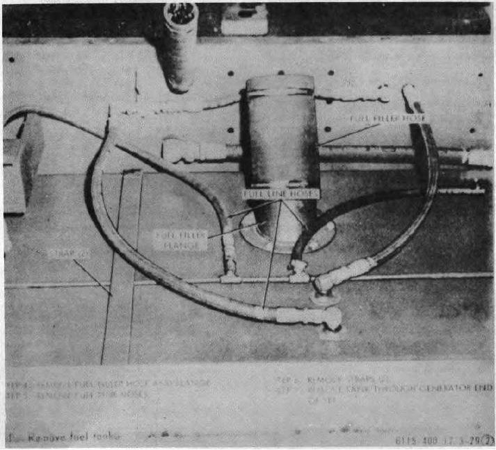
Figure 3-29 (2). Continued.
disconnect the relief valve-to-
(2) Check for an inoperative fuel
fuel tank return line from the
pressure relief valve or fuel transfer
relief valve.
pump as follows:
(c) Start engine and operate at 60
(a) Install a fuel pressure gage
cycles.
If gage indicates a
between the outlet of the F2
pressure below the specified
fuel filter and the inlet of the
minimum and a full flow of fuel
fuel injection pump.
is observed from disconnected
(b) Start engine and operate at 60
return line, the indication is that
cycles.
Observe the fuel
the pressure relief valve is stuck
pressure gage. Gage should
in the open position and the
indicate a pressure of 8 to 30
valve must be replaced as a
psi.
If gage indicates a
unit. However, if gage
pressure
below
specified
minimum, stop engine and
3-28