
TM 5-6115-400-12
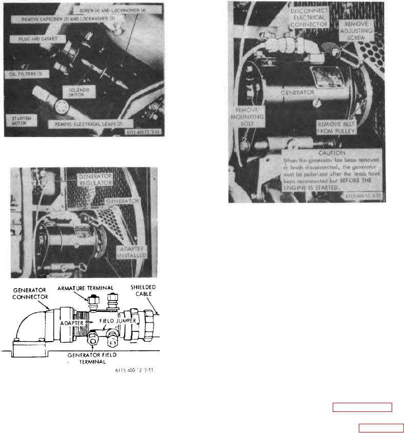
Figure 3-50. Starter motor and solenoid switch,
removal and installation.
Figure 3-52. Generator, removal and installation.
(2) Remove screw attaching brush lead to brush
holder.
(3) Remove brush from holder.
(4) Install new brushes in reverse order of removal.
3-58. Generator Regulator
a. General. The three-unit, heavy-duty generator
regulator automatically controls the output of the direct
current producing generator to keep the batteries fully
charged.
A circuit breaker unit closes the circuit
between the batteries and the generator when the
generator voltage is above the battery voltage and
opens the circuit when the condition is reversed. A
current regulator unit limits the current to the maximum
rated value of the generator. A voltage regulating unit
Figure 3-51,. Generator and regulator testing.
maintains the voltage of the system at the full charge
level.
c. Service Generator Brushes as Follows:
b. Equipment Testing. Refer to paragraph 3-57.
(1) Loosen cover band and slide sideways to
c. Removal and Installation. Refer to figure 3-53
provide access to brush area.
and remove generator regulator.
3-56