TM 5-6115-545-12
TO-35C2-344-1
NAVFAC P–8-626-12
TM-00038G-12
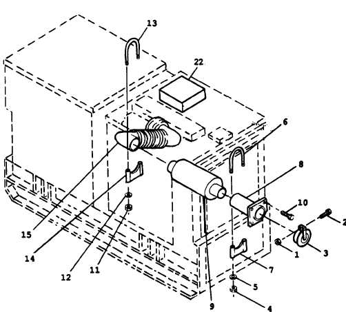
1. Nut
5. Washer
9. Muffler
13. u–bolt
22. Document Compartment
2. Screw
6. U-bolt
10. Screw
14. Bracket
3. Weather Cap
7. Bracket
11. Nut
15. Exhaust Pipe
4. Nut
8. Nozzle
12. Washer
16.-21. Deleted
Figure 3-12. Exhaust Pipe
Section XI. CONVENIENCE RECEPTACLE
3-88. General.
c. Remove grommet (12) from box (3) and feed
This section contains information on the convenience
electrical wires back through grommet hole. Tag all
receptacle and associated circuit breaker.
electrical connections for positive identification during
installation.
3-89. Convenience
Receptacle
Box
Assembly
d. Install new convenience receptacle box assembly
Replacement.
in reverse order of removal.
See figure 3-13 and proceed as follows
3-90. Convenience Receptacle Replacement.
Remove six screws (1) which secure box cover (2) and box
See figure 3-13 and proceed as follows
(3) to frame (4).
a. Remove six screws (1) which secure box cover (2)
b. Tilt box cover (2) and disconnect electrical
and box (3) to frame (4).
connections from receptacle (5) and circuit breaker (9) and
b. Tilt box cover (2) and disconnect electrical
remove box cover and assembly.
connections from receptacle (5).
3-32
Change 7