TM 5-6115-545-12
TO-35C2-3-444-1
NAVFAC P-8-626-12
TM-00038G-12
3.78 Replacement of Suppression Components, (Cont)
d. Main AC Contactor Three RFI suppression
capacitors C3, C4 and C5 are connected between terminals
A2, B2, and C2 respectively, of the main ac contractor CB2
and ground. Replace suppression capacitors as shown in A
of figure 3–11.
e. Day Tank Solenoid Valve. Diode suppressors
CR27 are provided at the connector of the day tank solenoid
valve. Replace diode suppressors as shown in B of figure
3-11.
3-79. Testing
of Radio Interference Suppression
Components.
Test the capacitors for leaks and shorts using a multimeter or
other capacitor tester. Replace defective capacitors. If test
equipment is not available and interference is indicated,
isolate the cause of interference by the trial and error method
of re- placing each component in turn until the cause of
interference is located and eliminated.
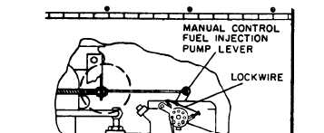
Figure 3-10. Lockwire of Fuel Injector Pump
for Class 2 Operation
Section VIII. ORGANIZATIONAL MAINTENANCE
3-80. General
maintain the engine generator set at the organizational level.
Instructions are provided in sections IX through XLIV for
Where essential, sections are arranged in the most logical
the information and guidance of responsible personnel to
order of disassembly of equipment.
Section IX. BATTERIES, AND RELATED PARTS
3-81. General.
This section contains information on the batteries,
battery tray and slave receptacles of the engine generator set.
Two 12-volt 100 ampere, lead acid type batteries are
mounted side by side on a battery tray. The batteries are
electrically connected in series to supply 24 Vdc for starting
the engine generator set. There is a slave receptacle
electrically connected in parallel with the batteries. The
receptacle facilitates external connection with the batteries,
in order to supply or receive an auxiliary source of electrical
power. A source of 24 Vdc electrical power is therefore
available for other development. Normally, the engine
generator set should be operating so as not to run down the
batteries when supplying this source of dc power.
3-82. Batteries.
a. Replacement. To replace one or both batteries, see
figure 3-4 and proceed as follows:
(1) Remove screw (lA), nut (lB) and clamp (lC).
Disconnect battery negative cable (1) positive cable (2) and
jumper cable (3) from storage batteries (4)
(2) Remove two nuts (5) and lockwashers (6),
which secure battery retainer (7) to studs (8), and remove
storage batteries (4).
(3) Install new storage battery in reverse order of
removal.
b.
Battery Testing.
NOTE
Failure to perform this task prior to
adding distilled water will result in an
erroneous reading.
Battery hydrometer readings should be tested on all
cells monthly. Always test a battery for a degree of charge
before adding water. The specific gravity between the cells
should be within .05. A dangerously low point of charge
indicated by a hydrometer reading of 1.150 or less will
permit the battery to freeze at a temperature of 5° F. A
specific gravity of 1.250 will permit the battery to withstand
temperatures as low as -65°F without freezing. An
acceptable hydrometer reading of 1.210-1.220 at 80°F will
be obtained from a fully charged battery (2.0-2.2 volts dc
per cell).
Battery reading of less than 1.200 or cell variance of .05
or greater will be replaced if attempts to restore the battery
fail. Compare specific gravity readings with previous
readings for cell deterioration.
NOTE
The 6TN and 6TL batteries can be mixed or matched.
However, maintenance–free batteries cannot be mixed or
matched with military batteries. The 6TN and or the 6TL
batteries will perform properly in hot weather as long as
electrolyte levels are carefully monitored. If the electrolyte
expands and causes the level to rise, some fluid must be
removed. If the level becomes too low due to evaporation,
distilled water may be used to obtain the proper level. A
good grade of drinking water (excluding mineral waters)
may be used if distilled water is not available.
Electrolyte (NSNs 6810-00-249-9354 and
6810-00-843-1640) have a specific gravity of 1.280 and
should be used in these batteries. Do NOT adjust the
electrolyte in wet batteries to a lower specific gravity.
Change 17
3-29


