S e c t i o n X I V .
P A R A L L E L I N G
R E C E P T A C L E S
3 - 9 7 .
G e n e r a l .
This section contains information on the paral-
leling receptacles of the engine generator set. The
paralleling receptacles provide a means of inter-
connecting three generator sets of the same class,
mode and size by the use of 25 foot, four conduc-
tor cables. The paralleling receptacles include
the wiring harness with connectors, protector caps
for the connectors, and the shorting plug dummy
connector.
3 - 9 8 .
R e p l a c e m e n t .
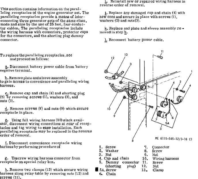
To replace the paralleling receptacles, see f i g u r e
3 - 1 6 and proceed as follows:
a. Disconnect battery power cable from battery
neg;tive terminal.
~. Remove plate and sleeve assembly
( p a r a
3 - 9 6 )
to gain access to convenience and paralleling wiring
harness.
c. Remove cap and chain (4) and shorting plug
(5) %y removing screws (l), washers (2), and
nuts (3).
Q. Remove screws (8) and nuts (9) which secure
receptacle in place.
e.
Using full wiring harness (10) slack avail-
abl~, discomect wiring connections at rear of recep-
tacles and tag wiring to ease installation. Each
paralleling receptacle may be replaced in the reverse
order of removal.
& Disconnect convenience receptacle wiring
harness by performing procedure of p a r a g r a p h 3 - 8 9 a
t h r o u g h
c .
—
—
g.
Unscrew wiring harness connector from
receptacle on special relay box.
~. Remove two clamps (13) which secure wiring
harness along relay table by removing nuts (12) and
screws (11).
i.
Reinstall new or repaired wiring harness in
rev%rse order of removal.
& Replace any damaged cap and chain (4) with
new ones and secure in place with screws (l),
washers (2) and nuts(3).
k. Replace and plate and sleeve assembly re -
moved in step b.
—
1. Reconnect battery power cable.
—
1.
Screw
7.
Connector
2.
Washer
8.
Screw
3.
Nut
9.
Nut
4. Cap and chain
10.
Wiring harness
5.
Dummy
connector
11.
Screw
(shorting
plug)
~~.
Nut
~ ;A. Screw
.
Clamp
.
Chain
F i g u r e
3 - 1 6 .
P a r a l l e l i n g R e c e p t a c l e s
C h a n g e 1
3 - 3 6