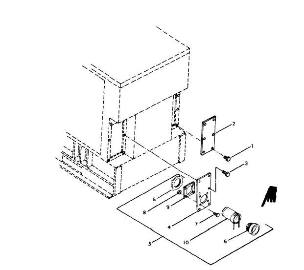
1. Screw
2. Cover
3. Screw
4. Plate
7. Screw
10. Cloth sleeve
5. Plate and sleeve assy
8. Nut
6. Bushing
9. Retaining plate
Figure 3-15.
Plate and Sleeve Assembly.
Section XIII. PLATE AND SLEEVE ASSEMBLY
3-95. General.
a. Remove screws (1) which secure cover (2) to
housing. Remove screws (3) which secure plate (4)
This section contains information on the plate and
of plate and sleeve assembly (5) to housing.
sleeve assembly. The plate and sleeve assembly
provides an opening for kit installation. and load
b. Remove screws (7) and nuts (8) which secure
cable, with a cover to secure the opening.
retaining plate (9) and cloth sleeve (10) to plate.
Remove bushing (6), cloth sleeve (10) and retain-
3-96. Replacement.
ing plate (9).
To replace the cover plate and sleeve assembly see
c.
Install a new plate and sleeve assembly, or
figure 3-15, and proceed as follows:
parts thereof, in the reverse order of removal.
Change 93-35

