T.O. 35C2-3-442-2
P-9-TM-457-35
TM 5-6115-457-34
TM-07464A-35
i s tripped, the solenoid plunger should
r e l e a s e (move out of the solenoid) and
This movement of the
r e m a i n released.
s o l e n o i d plunger should rotate the
m a n u a l fuel rack lever clockwise to
almost full off position.
c . UTILITY GOVERNOR SPEED SETTING
Adjust utility governor
ADJUSTMENT.
l o w and high speed stops as follows:
1. L o o s e n nut (5, figure 8-33)
and turn low speed stop screw (4)
c o u n t e r c l o c k w i s e until it is free of
s p e e d e r spring (46).
CAUTION
Do not crank engine for more
than 15 seconds at a time.
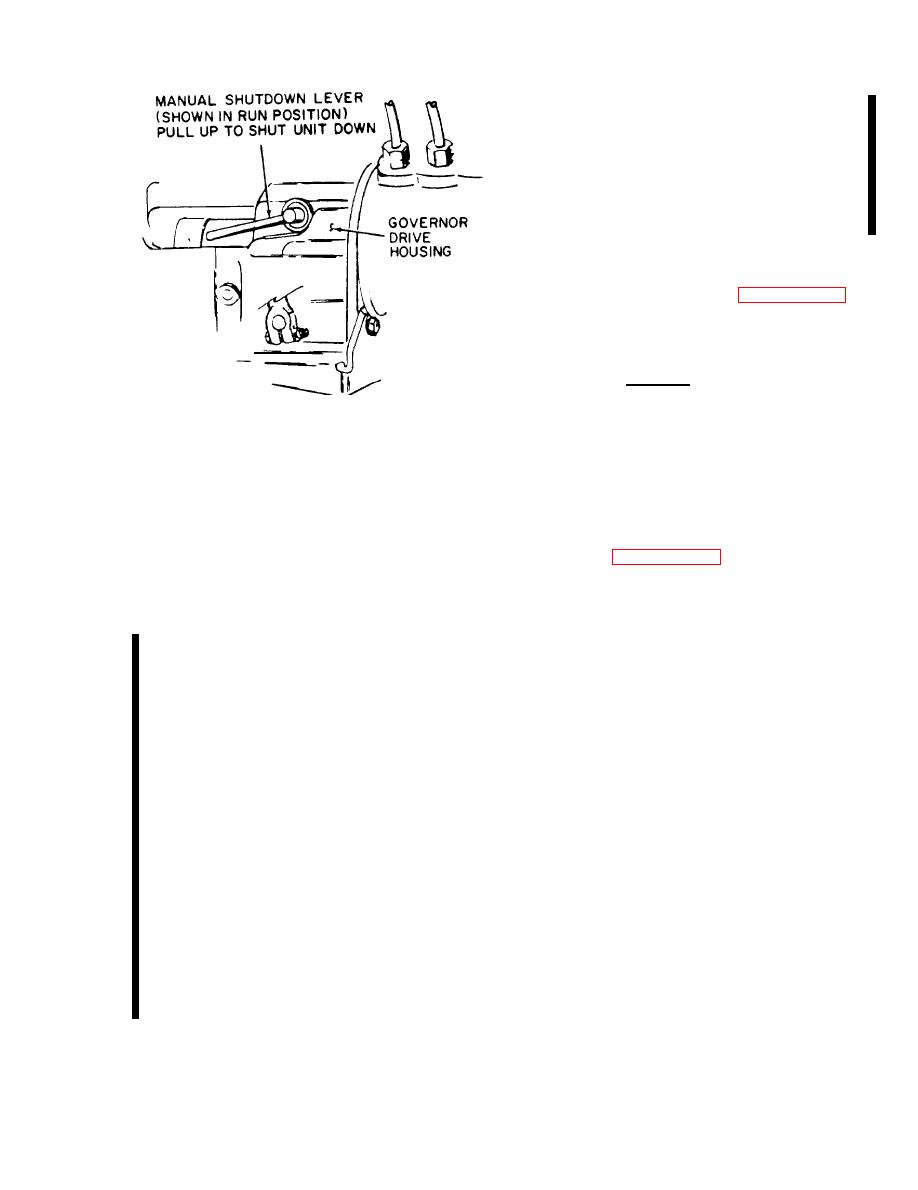
Figure 8-66. Location of manual fuel
P e r m i t starter to cool a mini-
shutdown lever
mum of three minutes between
crankings.
3. T u r n engine over using starter
u n t i l oil pressure builds up to 50 10
2. Crank engine over with
PSIG.
starter and turn low speed stop screw
O i l pressure should build up
within 15 seconds.
( 4 ) clockwise until governor output
shaft (13, figure 8-33) rotates, opening
f u e l rack. Continue turning low speed
Release manual fuel shutdown
4.
Inspect all fluid systems for
lever.
s t o p screw until engine starts.
s i g n s of leakage.
3. Permit engine to run a mini-
mum of five minutes for warmup and
b. OPERATIONAL TEST OF OVERSPEED
a d j u s t low speed stop screw (4) to
SHUTDOWN DEVICE.
obtain 800 RPM idle speed.
Clockwise
r o t a t i o n will increase speed. Hold screw
1. Dead crank engine and deter-
i n position and tighten nut (5). Recheck
n i n e if solenoid plunger (2, Figure
If the sole-
RPM setting.
8 - 3 1 A ) pulls in (bottoms).
noid plunger does not bottom or does not
4. R o t a t e speed adjusting shaft
have enough power to overcome the spring
(25) to maximum speed position and moni-
tension, increase the measurement
tor engine RPM. Do not exceed 2300 RPM.
between the bushings (6 and 9, Figure
3-31A) by adjusting bottom bushing.
5. Engine high speed stop
setting should be 2250 RPM. To adjust
2. Each time the engine is
h i g h speed stop, loosen nut (20) and
s t a r t e d , the solenoid plunger should
r o t a t e high speed stop screw (19) to
p u l l in (bottom) and remain pulled in.
obtain 2250 RPM when speed adjusting
This movement of the solenoid plunger
shaft (25) is in maximum speed position.
s h o u l d rotate the manual fuel rack lever
C l o c k w i s e rotation will increase engine
c o u n t e r c l o c k w i s e to almost full on
RPM setting. T i g h t e n lock nut and re-
position.
check RPM setting.
3. Each time the engine is
I f engine s u r g e s during
6.
stopped or t h e governor overspeed switch
8-147
Change 2


