T O 35C2-3-442-2
P-8-627-34
TM-07464A-35
T M 5-6115-457-34
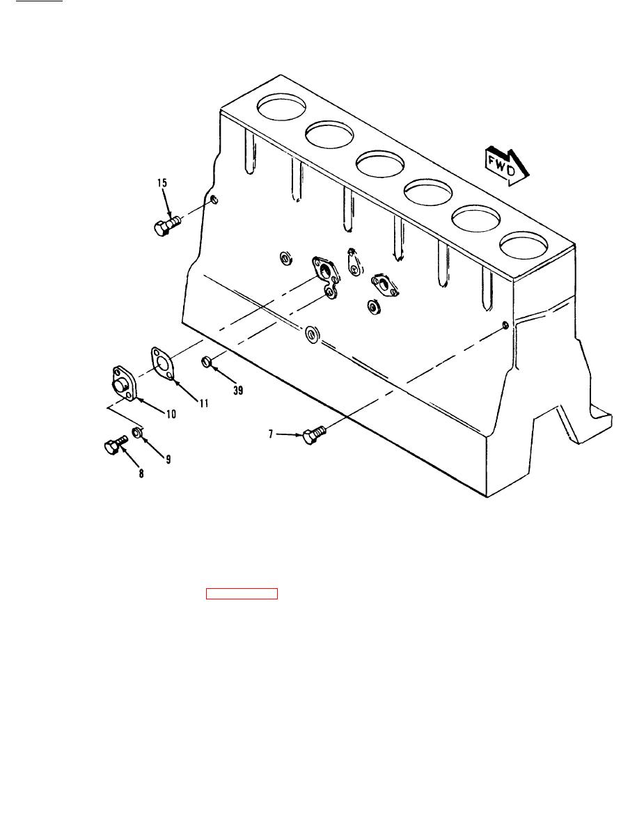
Figure 8-64.
Cylinder block and covers group, exploded view
(sheet 2 of 2)
c . Position cylinder liner (12, fig-
b. Coat seals (13, figure 8-64) and
mating bore with liquid soap before instal-
ure 8-64) in bore chamber. Place a
ling cylinder liner (12).
suitable plate on top of cylinder liner (12).
Use a block of hard wood over the plate and
NOTE
drive cylinder liner (12) into place.
Cylinder liner shall be installed in
d. Secure cylinder liner (12) in its bore
s a m e cylinder bore from which it
using a suitable crossbar and two 5/8 inch
w a s removed.
NC bolts with flat washers as shown in
8-143
Change 8


