T. O. 35C2-3-442-2
P-9-TM-457-35
TM 5-6115-457-34
TM-07464A-35
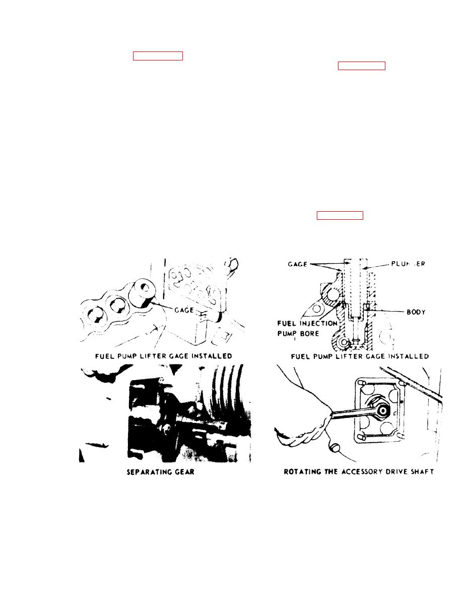
b. FUEL INJECTION PUMP TIMING
2. Apply 1875 PSI to the valve
DIMENSION CHECK AND ADJUSTMENT -
assembly (13, figure 8-39), a satisfactory
ON ENGINE (See figure 8-44).
valve should emit a complete atomized
spray with a sharp cut-off of fuel and no air
1. Remove two bolts and lockwash-
dribble. If the valve assembly (13) emits a
ers and timing pointer cover from flywheel
solid stream of fuel with little or no
housing.
atomization, replace the nozzle assem-
bly (16).
2. Remove fuel injection pump for
Cylinder No. 1 as outlined in para-
3. Valve assembly (13) unseating
graph 8-143.
pressure should be between 400 to 800 PSI.
If valve assembly fails to reach a minimum
3. Rotate crankshaft counterclock-
of 400 PSI, replace valve assembly (13).
wise (as viewed from flywheel end) at least
Reduce gauge pressure to 300 PSI. Observe
60 degrees. Continue rotating crankshaft
the gauge and note whether leakage causes
counterclockwise until TC1-6 CYL mark
an additional drop in pressure. If the pres-
on flywheel is aligned with timing pointer
sure falls more than 100 PSI in 30 seconds,
as shown in figure 8-45 and both the inlet
replace the nozzle assembly (16).
Figure 8-44. Fuel injection timing on the engine
8-93


