T.O. 35C2-3-442-2
P-9-TM-457-35
TM 5-6115-457-34
TM-07464A-35
9. Install fuel injection pump for
Cylinder No. 1 as outlined in para-
graph 8-148.
10. Install timing pointer cover and
two bolts and lockwashers on flywheel
housing.
NOTE
Timing the fuel injection pump on
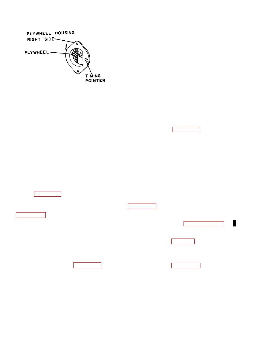
Figure 8-45. Aligning timing pointer
engine will take into consideration
on flywheel
a slipped accessory drive shaft
coupling or worn timing gears.
and exhaust valves of Cylinder No. 1
c. FUEL INJECTION PUMP TIMING
are closed.
DIMENSION CHECK AND ADJUSTMENT -
(OFF ENGINE (See figure 8-46).
4. Install a suitable gauge in pump
bore. Measure timing dimension using a
NOTE
depth micrometer. Timing dimension
should be 4.2159 to 4.2199 inches. If
Timing the fuel injection pump
timing dimension is correct, proceed to
off engine will adjust for wear on
step 9. If timing dimension is not correct,
the fuel injection pump only.
proceed to step 5., and make an adjustment.
1. Install a suitable pointer assem-
5. Remove small cover (24, fig-
bly on fuel injection pump housing.
ure 8-29) from front of timing gear cover
(50) and loosen accessory drive gear retain-
2. Install a suitable timing plate on
ing nut (figure 8-44) (do not remove nut).
drive end of fuel injection camshaft (60,
6. Using a suitable gear pulling tool,
separate gear from accessory drive shaft
3. Remove fuel injection pump for
7. Turn accessory drive shaft
cylinder being checked (paragraph 8-143).
extension counterclockwise and adjust
Install a suitable gauge in pump bore.
timing dimension. Timing dimension
should be 4.2159 to 4.2199 inches. If
4. Refer to table 8-1 and select the
timing dimension is within specified depth
timing plate degree setting for lifter being
range, proceed to step 8. If timing dimen-
checked. Rotate timing plate counterclock-
sion is not within specified depth range,
wise until proper degree setting aligns with
replace worn spacer (55, figure 8-39) with
pointer assembly (figure 8-46). Tighten
an approved spacer of additional thickness.
screw to lock in position.
8. Install accessory drive gear.
5. Measure timing dimension using
Tighten retaining nut from 90 to
a depth micrometer. Timing dimension
110 foot-pounds. Recheck timing dimen-
should be 4.2670 to 4.2680 inches. If
sion. Replace cover.
timing dimension is correct, proceed to
8-94
Change 1


