P-8-627-34
T O 35C2-3-442-2
TM-07464A-35
TM 5-6115-457-34
g. Inspect threaded holes for damaged
threads.
h . Discard seals.
8-146. REPAIR.
a. Repair minor nicks and burrs on
fuel rack (40, figure 8-39) using a suitable
file or hone.
WARNING
Fuel Oil if flammable and moderately
toxic to skin, eyes and respiratory
t r a c t . Eye and skin protection re-
quired. Good general ventilation
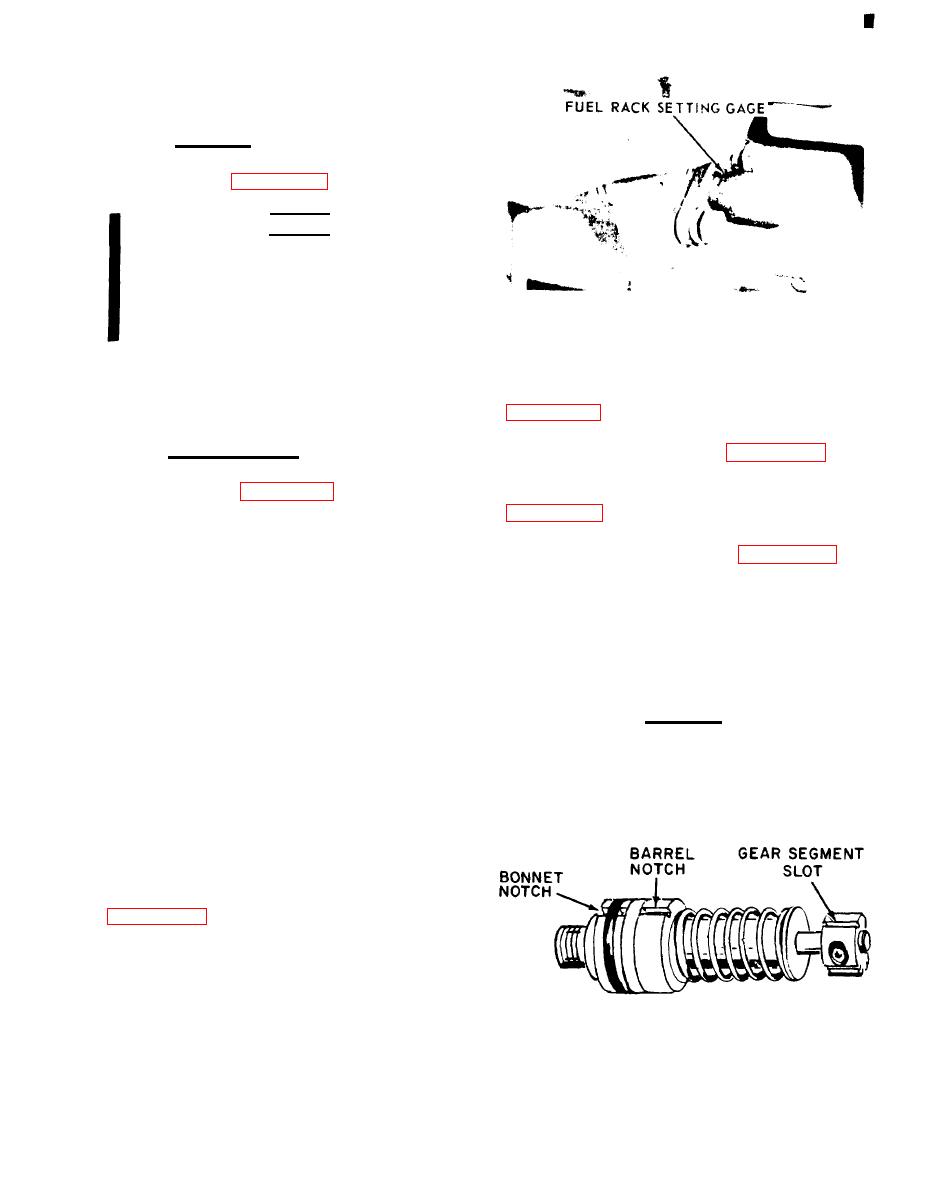
Figure 8-41. Installing regulator fuel rack
is normally adequate.
b. Ream out clogged passages in hous-
ing (76) with a thin flexible wire. After
pump, align the notches in the bonnet (44,
cleaning passages, flush with fuel oil.
c. Repair minor thread damage using
alignment mark 180 degrees from the pump
a suitable thread chaser.
8-147. REASSEMBLY.
gear segment center tooth {figure 8-42).
Position pump so that the notches align
Refer to figure 8-39 and reassem-
with the two locating dowel pins (70 and 72,
ble fuel injection group in the reverse order
of index numbers assigned. Pay particular
pump gear segment center tooth with fuel
attention to the following:
regulator rack center notch (figure 8-43).
Install pump. Keep a downward force on
a. All assembly should be done with
the pump, and install bushing (42, fig-
clean hands and on a clean, lint-free cloth.
ure 8-39) until flush with the top of the
housing. If the bushing cannot be installed,
b. Using a suitable installing tool,
this far by hand, remove bushing, realign
install camshaft bearing (63) so that hole in
component parts, and install again.
bearing aligns with oil passage in housing
(76) and is flush with housing face.
CAUTION
When tightening bushing (42), a
c. Install fuel regulator rack bearings
lesser torque value will allow pump
(62 and 65) so that groove in bearings
aligns with scribe marks on housing (76).
to leak; a greater torque value can
Bearing (65) must be installed 0.195
damage housing.
0.005 inch deep from the housing face.
d. Use a suitable fuel rack setting
gauge when installing fuel regulator rack,
so that gauge indicates 0.00 inch.
e. Use the same extractor that was
used to remove each pump to install each
fuel injection pump. Sighting down the
Figure 8-42. Fuel injection pump alignment
8-91
Change 8


