TM 9-6115-662-13&P
CAUTION
2.
3.
4.
5.
6.
7.
The control panel connector P3 is connected to connector J4. Movement of the switch box
cover is limited. To prevent damage to control panel wiring harness, use caution
removing switch box cover. Failure to observe this caution can result in equipment
damage.
Carefully position switch box cover (4) in front of switch box.
Disconnect P3 (7) from J4 (8) and set switch box cover (4) out
Remove switch box cover (4).
NOTE
of the way.
The bus bar is physically connected to L0 of the switch box assembly and is a common
ground. Leads connected to bus bar maybe connected to any terminal on the bus bar.
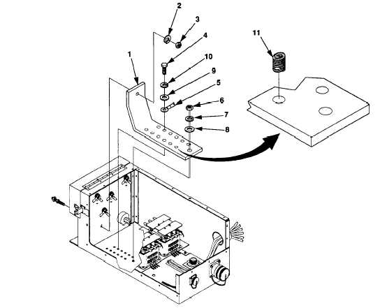
Remove cap screws (4, figure 5-14), lock washers (10), flat washers (9), and electrical leads (5) from
bus bar (1).
Remove nut (3) and lock washer (2).
Remove nut (6), lock washer (7), flat washer (8), and bus bar (1).
Figure 5-14. Bus Bar Maintenance
5-28

