
ARMY TM 5-6115-633-14&P
(f) Position cover (4) on switch box (5) and secure with 16 screws (1), 16 Iockwashers (2)
and 16 flat washers (3).
c. Switch to Load Terminal Wire Replacement. (See figure 4-12.) There are three wires
connecting the switch to the load terminals. When attaching wires, refer to the schematic inside the
switch box (figure 4-7 or 4-8, as applicable) and to the identification bands on the wires.
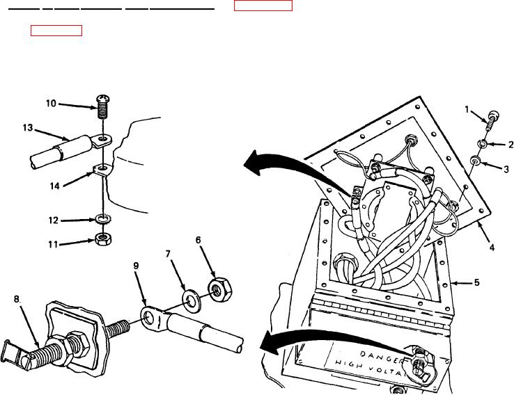
Figure 4-12. Switch to Load Terminal Wire Replacement.
(1) Removal.
(a) Remove 16 screws (1), 16 Iockwashers (2), and 16 flat washers (3) securing cover (4)
to switch box (5) and take cover off switch box
(b) Remove nut (6)and flat washer (7) from load terminal stud (8) inside switch box (5).
Slide wire terminal (9) off stud.
NOTE
When removing more than one wire, tag switch terminals for identification.
(c) Remove screw (10), nut (11) and star washer (12) securing wire terminal (13) to
switch terminal (14). Take wire off switch.
4-24