
ARMY TM 5-6115-633-14&P
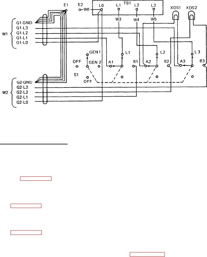
Figure 4-8. Five- Wire Switch Box Schematic Diagram.
b. Switch Box Internal Wiring Test.
(1)
Set multimeter for continuity testing.
Test wires between switch terminals and load terminals by touching probes to each of the
(2)
following pairs of test points: L1 on switch to L1 load terminal, L2 to L2, and L3 to L3. If
multimeter does not indicate continuity between each pair of test points replace associated
wire (paragraph 4-25, c.).
Test wires and socket associated with GEN 1 indicator light by testing for continuity between
(3)
switch terminal A2 and socket XDS1, and switch terminal A3 and socket XDS1. If multimeter
does not indicate continuity exists on both of these wires, replace light and wire assembly
(paragraph 4-25, b.).
(4)
Test wires and socket associated with GEN 2 indicator light by testing for continuity between
switch terminal B2 and XDS2 socket, and switch terminal B3 and XDS2 socket. If multimeter
does not indicate continuity exists on both of these wires, replace light and wire assembly
(paragraph 4-25, b.).
On 5-wire switch box only, test ground wire by touching one probe to switch box load term-
(5)
inal L0 and touch remaining probe to AC GROUND terminal E2 on switch box. If multi-
meter does not indicate continuity, replace associated wire (paragraph 4-25, e.).
4-19