
ARMY TM 5-6115-633-14&P
c. Switch Test.
(1) Set multimeter for continuity testing.
(2) Set switch lever to GEN 1 position.
(3) Touch one probe to switch terminal A1 and remaining probe to switch terminal L1. Repeat
test between terminals A2 and L2, and terminals A3 and L3. If multimeter does not indicate
continuity exists between each pair of terminals, switch is defective. Notify higher level of
maintenance.
(4) Set switch lever to GEN 2 position and repeat step (3) above, substituting terminals B1, B2
and B3 for A1, A2 and A3.
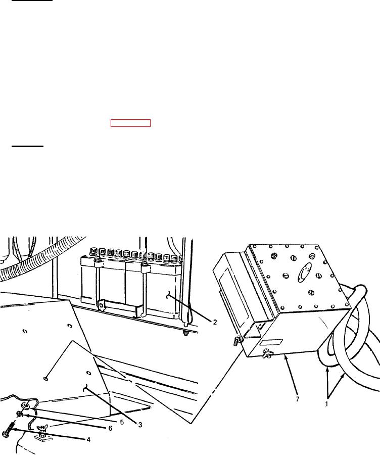
4-24. Switch Box Replacement. (See figure 4-9.)
a. Removal.
(1) Detach power cables (1) from load terminals on generator sets (2). (Refer to TM 5-6115-
585-12.)
(2) Working underneath roadside fender (3), remove four screws (4), four flat washers (5)
and four Iockwashers (6) securing switch box (7) to fender.
(3) Lift switch box (7) off fender.
Figure 4-9. Switch Box Replacement.
4-20