
ARMY TM 5-6115-633-14&P
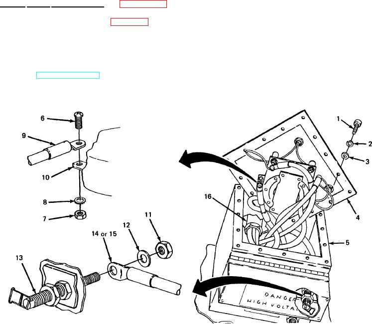
(2) Installation.
NOTE
Observe identification tags on switch terminals when installing wires.
Position wire terminal (9) against underside of switch terminal (13). Insert screw (10)
(a)
up through wire terminal and switch terminal. Install star washer (12) and nut (11) on
screw and tighten against switch terminal.
(b)
Slide terminal (9) at free end of wire onto load terminal stud (8) and secure with flat
washer (7) and nut (6).
Position cover (4) on switch box (5) and secure with 16 screws (1), 16 Iockwashers (2)
(c)
and 16 flat washers (3).
d. Power Cable Replacement. (See figure 4-13.) There are two power cables on the power
plant - one for each generator set. This procedure is typical for both. When attaching wires, refer to
the schematic inside the switch box (figure 4-7 or 4-8, as applicable) and to the identification bands
on each of the five wires that make up each cable.
(1) Removal.
(a) Disconnect power cable from load terminals on generator set. (Refer to
Figure 4-13. Power Cable Replacement.
4-25