
ARMY TM 5-6115-633-14&P
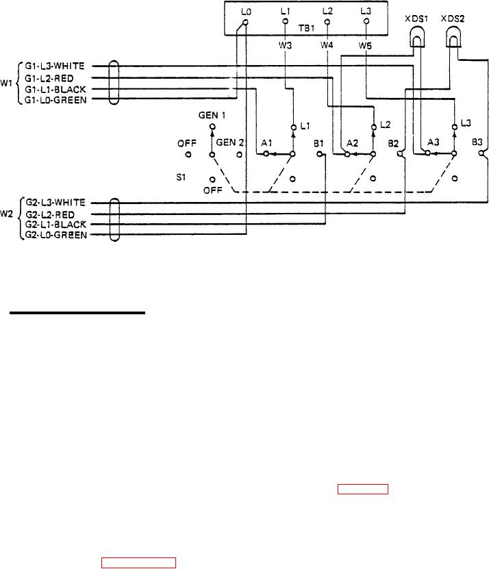
Figure 4-7. Four- Wire Switch Box Schematic Diagram.
a. Power Cable Assembly Test.
(1)
Set multimeter for continuity testing.
(2)
Set switch box rotary switch to GEN 1 position and locate power cable assembly associated
with that switch position.
Test white wire by touching one probe of multimeter to load terminal L0 on generator set
(3)
and touching other probe to load terminal L0 on switch box. Multimeter must indicate
continuity between these points.
(4)
Repeat step (3) for black wire (between L1 on generator set and A1 on switch), red wire
(between L2 on generator set and A2 on switch) and blue wire (between L3 on generator
set and A3 on switch).
(5)
On power plants supplied with the 5-wire configuration switch box (figure 4-8), the green
(ground) wire must also be tested. Disconnect wire from frame ground stud under gener-
ator set control panel. Test for continuity between free end of wire and ground stud E1 on
switch box.
If multimeter does not indicate continuity exists on each wire in the cable, replace power
(6)
cable assembly (paragraph 4-25, d.).
To test power cable assembly associated with GEN 2 switch position, perform steps (2)
(7)
through (6) substituting switch terminals B1, B2 and B3 for terminals A1, A2 and A3, as
test points. Generator set load terminal designations and wire color-coding is identical for
both power cables.
4-18