
ARMY TM 5-6115-633-14&P
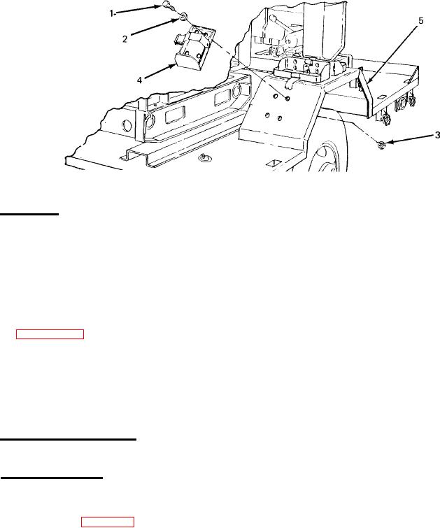
Figure 4-6. Fire Extinguisher Bracket Replacement.
b. Installation.
(1) Position fire extinguisher bracket (4) on fender (5).
(2) Insert four screws (1) with four washers (2) down through bracket (4) and through
fender (5).
(3) Install one nut (3) on each screw (1). Tighten hardware to secure bracket (4).
4-21.
Leg Prop Assembly Servicing. Servicing of the leg prop assembly is limited to semiannual
lubrication (paragraph 4-9, b.).
Section IX. MAINTENANCE OF ELECTRICAL SYSTEM
4-22.
General. This section contains maintenance information on electrical components unique to
the power plant end item. For all other electrical system maintenance, refer to the applicable
generator set and trailer manuals as follows:
a. Generator Set Maintenance. For generator set maintenance procedures, refer to TM 5-6115-
585-12.
b. Trailer Maintenance. For trailer maintenance procedures, refer to TM 9-2330-213-14&P.
4-23.
Switch Box Testing. To isolate the source of an electrical system problem, perform continuity
tests on the components of the switch box as described below. Refer to the schematic diagram inside
the switch box (shown in figure 4-7 or 4-8, as applicable) to locate and identify the test points
indicated in these procedures.
4-17