TM5-6115-593-34
NAVFAC P-8-631-34
TO-35C2-3-463-2
13-23.
TIMING GEAR AND COVER. To inspect and
replace the timing gear and cover, refer to figures 13-
36, and 13-37, and proceed as follows:
a. Removal. Proceed as follows:
(1) Remove 26 screws (27, figure 13-36) and
two screws (20) and lockwashers (21).
(2) Install two 6-inch (152 mm) guide studs
through top of gear case into block to pre-
vent gear case from falling during removal.
(3) With a soft hammer, tap case alternately
top and bottom, left and right, to drive from
dowels.
(4) Lift gear case from guide studs and remove
studs from block.
(5) Remove
capscrew
(1,
figure
13-37)
lockwasher (2), front thrust washers (4 and
5), gear and bushing (7 and 8) and rear
thrust washer (5).
b.
Inspection.
(1) Inspect gear for cracks, broken teeth, or
visible wear. Replace if damaged or
excessively worn.
(2) Inspect gear case for cracks, burrs, or
breaks. Replace if damaged.
(3) Inspect screw threads and repair with heli-
coil inserts if found damaged.
(4) Inspect dowels for damage; replace or bore
out for oversize if required.
c.
Installation.
(1) Install thrust washer (5, figure 13-37) on
idler shaft (6) with oil grooves facing away
from shaft shoulder.
(2) Insert dowel pin (3) in drilled hole in end of
idler shaft (6), if removed.
(3) Install timing gear (7) on shaft (6) indexing
two "O" marks on gear astride single "O"
mark on crankshaft gear.
(4) Install outer thrust washers (5 and 4) over
shaft with oil grooves next to idler gear.
(5) Install lockwasher (2) and screw (1).
(6) Timing gear thrust limit is 0.001 to 0.016
inch (0.03 to
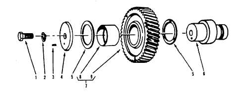
LEGEND
1.
Screw
4. Washer
7.
Idler gear assy
2.
Lockwasher
5.
Washer
8.
Bushing
3.
Pin 6. Shaft
9.
Gear
Figure 13-37. Timing Gear, Exploded View
13-73