TM5-6115-593-34
NAVFAC P-8-631-34
TO-35C2-3-463-2
(5) Drive ring gear (5) from flywheel with a
blunt chisel.
(6) Install two 5/8-11 studs in block to guide
flywheel housing during removal.
(7) Drive housing from dowels by tapping on
back side with a soft hammer or wooden
block. Using a suitable hoist, lift housing
from guide studs.
c.
Installation
(1) Install housing on dowels by tapping with a
soft hammer or wooden block.
(2) If an oven with heat control is not available,
heat ring gear (5) with a heating torch from
inside diameter so heat travels outward to
teeth.
(3) Use a Templistick crayon or equivalent to
determine amount of heat applied.
(a) Stroke gear with 600°F (316C) crayon
several times while applying heat.
(4) The crayon will leave a chalk mark until
temperature reaches 600F (316C). At
600F (316C), the crayon will leave a liquid
smear.
CAUTION
Overheating
to
temperatures
above
660°F (349°C) will soften gear.
(5) Place ring gear on flywheel and quickly
drive onto flywheel until gear is firmly
seated.
(6) Index the zero on crankshaft with the zero
on flywheel and assemble flywheel over
studs to crankshaft flange.
(7) Insert lockwashers (2) and screws (1).
Tighten screws alternately, a little at a time,
to pull flywheel up evenly. Continue until all
screws are tight.
(8) Attach indicator gauge to side of flywheel
housing to indicate bore of flywheel. The
total indicator reading must not be greater
than 0.005 inch (0.13 mm).
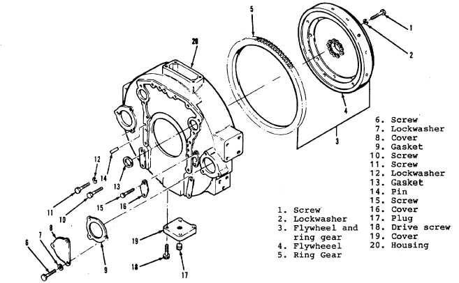
Figure 13-35A. Ring Gear, Flywheel, and Flywheel Housing
13-71