TM5-6115-593-34
NAVFAC P-8-631-34
TO-35C2-3-463-2
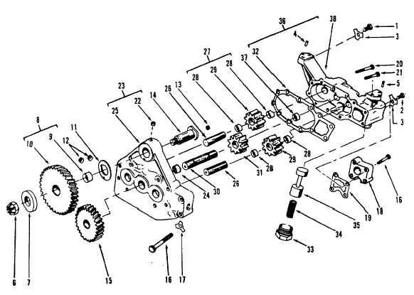
Figure 13-35. Oil Pump, Exploded View
LEGEND
1.
Screw
10.
Gear
20.
Screw
30.
Shaft
2.
Screw
11.
Washer
21.
Screw
31.
Gear
3.
Lockplate
12.
Plug
22.
Plug
32.
Gasket
4.
Dowel
13.
Plug
23.
Cover
33.
Cap
5.
Dowel
14.
Shaft
24.
Bushing
34.
Spring
6.
Nut
15.
Gear
25.
Cover
35.
Plunger
7.
Spacer
16.
Screw
26.
Shaft
36.
Body
8.
Gear and bushing
17.
Lockplate
27.
Gear
37.
Bushing
9.
Bushing
18.
Connection
28.
Bushing
38.
Body
19.
Gasket
29.
Gear
(1) Place plunger (35) and spring (34) in body
and secure with cap (33).
(2) Press internal drive gear (31) onto short end
of drive shaft (30) until shaft extends
through gear 1.020 to 1.040 inch (25.91 to
26.41 mm).
(3) Install drive shaft assembly in pump body.
(4) Press external drive gear (15) on drive
shaft, leaving 0.061 to 0.063 inch (1.55 to
1.60 mm) end thrust.
(5) Press in intermediate drive gear shaft (14)
until it seats. Mount thrust washer (11),
intermediate drive gear (8), spacer (7) and
nut (6) Torque nut (6) to 70 to 80 foot-
pounds (95 to 108 joules).
(6) Place idler gears (29) in pump body. Install
shafts
13-69