TM5-6115-593-34
NAVFAC P-8-631-34
TO-35C2-3-463-2
(3) Install vibration damper (3) and fasten with
washer (2) and screw (1); torque screw to
450 to 500 foot-pounds (610 to 678 joules).
(4) Install six screws securing vibration damper
(3). Torque conical screws to 70 to 80 foot-
pounds (95 to 108 joules). Torque hexagon
head capscrews to 100 to 120 foot-pounds
(136 to 163 joules).
NOTE
Crankshaft must be kept to front or rear
limit of thrust clearance while wobble is
being checked.
CAUTION
Do not pry against or strike damper.
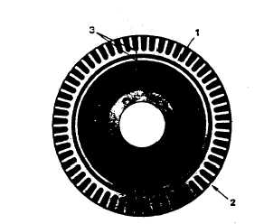
(4) With a dial gauge mounted to gear case
cover and arm resting on the inner
machined surface of the outer member,
check vibration damper eccentricity and
wobble at points (1) and (2) as show in
figure 13-32. Wobble must not exceed
0.009 inch (0.23 mm) per inch of radius.
Eccentricity must not exceed 0.030 inch
(0.76 mm).
Figure 13-32. Vibration Damper Wobble Check
Points
13-19.
ENGINE FRONT SUPPORT. To inspect and
replace the engine front support, refer to figure 13-33,
and proceed as follows:
a. Inspection. Inspect the engine front support for
signs of cracking or other signs of damage.
Replace if necessary, as follows:
b.
Removal.
(1) Refer to Chapter 2, Section IV to remove
engine assembly.
(2) Remove screws (4), lockwashers (5), screws
(6), and lockwashers (7).
(3) Remove
screws
(1),
nuts
(3),
and
lockwashers (2).
c.
Installation.
(1) Install new engine front support screws (1),
lockwashers (2), and nuts (3).
(2) Replace engine assembly.
(3) Install
lockwashers
(7),
screws
(6),
lockwashers (5), and screws (4).
13-20
OIL PAN ASSEMBLY. To replace or repair the
oil pan assembly, refer to figure 13-34, and proceed as
follows:
a.
Removal.
(1) Drain
oil
in
accordance
with
the
Operator/Crew
and
Organizational
Maintenance manual.
(2) Disconnect temperature sensor (34, figure
13-34) electrical connector. Remove screw
and washer securing temperature sensor
cable clamp, then move and secure cable
away from work area.
(3) Disconnect engine preheat hose coupling on
radiator line and two couplings on preheater
assembly, then remove three screws and
washers securing preheat hose support
brackets to engine. Move and secure
preheat hoses away from work area.
(4) Remove four nuts and washers from
preheater assembly V-bolts, then move and
secure preheater assembly away from work
area.
13-64