TM 5-6115-584-12
NAVFAC P-8-622-12
TO-35C2-3-456-1
TM-05682C-12
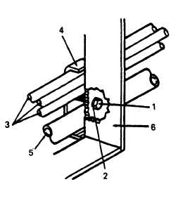
1. Screw (2)
4. Hold-down assembly (2)
2. Lockwasher (2)
5. Fuel drum adapter
3. Ground rod
6. Skid-base
Figure 3-3. Ground Rod and Fuel Drum Adapter Hold-Down
b. Cleaning and Inspection.
(1) Ground Rod. Inspect ground rod for damage and
corrosion. Pay particular attention to the threaded portions
of each piece, making certain the three pieces can be
properly assembled.
(2) Fuel Drum Adapter. Inspect adapter (5) for
cleanliness and condition of threaded portions. Clean
adapter with cleaning solvent and dry.
a. Inspect (see figure.3-5).
(3) Hold. down. Check hold-down assembly (4) for
physical damage and check condition of hardware (1
and 2).
c. Installation.
(1) Hold-down. Position lockwashers (2) on screws
(1) and insert into holes in skid-base (6). Position hold-
down assemblies (4) against skid-base (6), then start
screw (1).
Do not over-tighten screws as
hold-down assemblies may occur.
damage to
(2) Ground Rods and Fuel Drum Adapter. Slide fuel
drum adapter (5) and three piece ground rod assembly (3)
between hold-down assemblies (4) and skid base (6).
Tighten screws (1).
3-13. FUEL TANK ASSEMBLY.
a. Cleaning and Inspection (see figure 3-4).
(1) Fuel Tank Strap Assemblies. Inspect both straps
(1) for damage that would prevent them from securely
holding fuel tank (4) to skid-base (10). Check that both
straps are tight. Tighten straps by tightening nuts (2) and
washers (3) securing each strap to skid-base.
(2) Fuel Tank. Visually check fuel tank (4) for dents
or leaks. Check that filler cap (8) fits securely onto tank and
that filler cap and surrounding area is clean. Clean using
solvent and clean cloth.
(3) Fuel Level Gauge. Check fuel level gauge (6) for
physical damage. Check that gauge shows FULL when tank
is full, and EMPTY when tank is empty. Notify higher level
of maintenance for replacement of fuel level gauge.
(4) Float Switch. Inspect float switch (7) for physi-
cal damage. Check that float switch is properly attached to
tank.
(5) Fittings. Inspect three fittings (5) for physical
damage. Check that fittings are secured to fuel tank. Notify
higher level of maintenance of leaky or damaged fittings.
(6) Fuel Drain Valve. Inspect drain valve (9) for
physical damage, Check that valve operates properly. If not,
notify higher level of maintenance.
(7) Filler Cap Assembly. Inspecl filler cap (8) for
physical damage. Check that vent on underside of oap opens
and doses easily. Ensure that vent on underside of filler cap
is open before starting generator.
3-14. SHUTTER BOX ASSEMBLY.
Do not operate unit if shutter assembly is
not operating properly.
(1) Shutter Assembly. Check shutter assembly with
unit running under normal operating conditions. When
engine is cold, shutter assembly should be fully closed.
When engine warms up, shutter assembly should be fully
open at 140°F (60°C) or above at full rated load. Make
certain shutter assembly is free of dirt and oil which could
cause shutters to stick.
3-10
Change 7