TM 5-6115-584-12
NAVFAC P-8-622-12
TO-35C2-3-456-1
TM-05682C-12
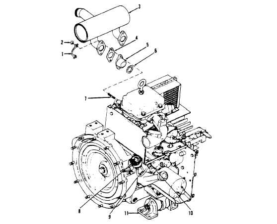
1. Lock tab (2)
5. Adapter (2)
8. Oil pressure gauge
2. Nut (4)
6. Adapter gasket (2)
9. Oil hose
3. Muffler
7. Stud (4)
10. Oil pressure switch
4. Muffler gasket (2)
11. Engine mount
TS 6115-584-12/3-6
Figure 3-6. Exhaust Muffler Assembly
3-15. EXHAUST MUFFLER ASSEMBLY
Check to see that exhaust is not obstructed and there
is no evidence of leaks.
3-16. ENGINE STARTER ASSEMBLY
Do not touch muffler assembly while unit is
running or immediately after shutdown, as
severe burns may result.
a. Cleaning and Inspection (see figure 3-7). On ASK equipped
generators, remove BATTERIES access door. Clean engine starter
a. Inspect (see figure 3-6). Manually open shutter
(1) by removing loose dirt with a stiff nonmetallic brush. Clean off
assembly and check that muffler assembly (3) is
remaining dirt and oil with dry cleaning solvent (Fed. Spec.
securely fastened to unit. Check that nuts (2) and lock
P-D-680). Inspect starter to see that electrical connections (4) are
tabs (1) attaching muffler to unit are in place.
clean and tight. Check to see that mounting bolts (2) are tight.
Check starter (1) for physical damage.
Change 7
3-13